Installation of the connectors, Connection to sunny boy inverters, Connection to a pc – SMA Sunny Boy Control Light User Manual
Page 20: Cabling a pc with rs232, 3 installation of the connectors, 1 connection to sunny boy inverters, 2 connection to a pc, 1 cabling a pc with rs232
Sunny Boy Control Light
Chapter 3: Installing of the connectors
SUNBCL-11:NE
- 20 -
SMA Regelsysteme GmbH
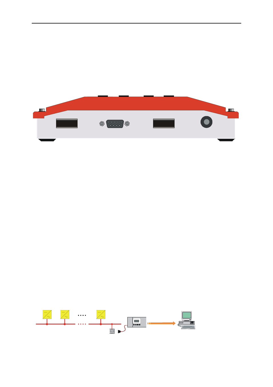
3 Installation of the Connectors
In the following chapters we define all possible connections for the Sunny Boy
Control Light.
LINE
90...260 V , 50/60 Hz
AC
RELAIS OUT
PC
(COM 2)
Sunny Boy
(COM 1)
Fig. 3.1: Bottom View of the Sunny Boy Control Light with interfaces and connectors
3.1 Connection to Sunny Boy Inverters
The data transmission is done via Powerline Communication
The Sunny Boy Control Light is therefore connected to the Sunny Boy inverters
by simply inserting the plug into the electricity socket.
3.2 Connection to a PC
The PC is connected to the Sunny Boy Control Light directly with RS232 or a
modem via telephone line for remote PV-plant management.
3.2.1 Cabling a PC with RS232
Sunny Boy
Sunny Boy
Sunny Boy
230 V / 50 Hz
Sunny Boy
Control Light
Modem elimination
cable
RS 232
PC
Fig. 3.2: Connection to a PC with RS232.