SMA Sunny Boy Control Light User Manual
Page 21
Sunny Boy Control Light
Chapter 3: Installing of the connectors
SUNBCL-11:NE
- 21 -
SMA Regelsysteme GmbH
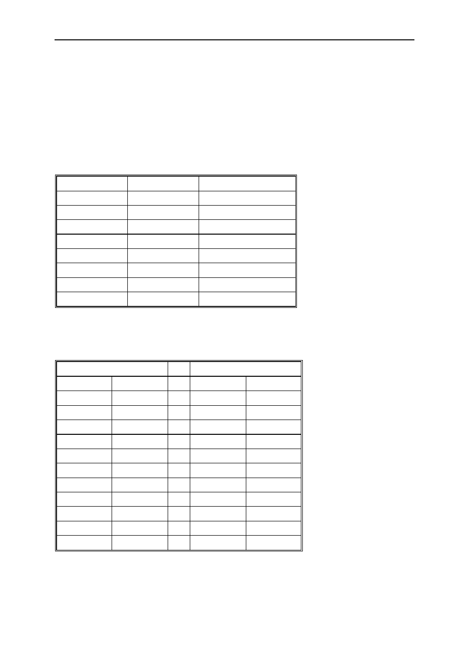
The PC is connected via RS232 with a PC data cable (SMA ordering No. 36-5001).
Note that is may be necessary to use a DB9 to DB25 adapter plug. (SMA ordering
No. 35-5010)
Pin Layout
PIN Signal
RS232 Description
1
DCD
Data Carrier Detect
2 /RXD
Receive
Data
3 /TXD
Transmit
Data
4
DTR
Data Terminal Ready
5 GND Ground
6
DSR
Data Set Ready
7
/RTS
Ready To Send
8 /CTS
Clear
ToSend
Fig. 3.3: Connecting Configuration Device PC (COM2)
Pin Layout of a DSUB9<>DSUB9 cable
DSUB9 socket
DSUB9 socket
Signal PIN
PIN Signal
/RXD 2
<>
3 /TXD
/TXD 3
<>
2 /RXD
GND 5
<>
5 GND
|
1
DCD
|
6
DSR
RTS 7
<>
8 CTS
DCD 1
|
DSR 6
|
CTS 8
<>
7 RTS
Fig. 3.4: PIN designation of a PC data cable DSUB9<>DSUB9