SMA Sunny Boy Control Light User Manual
Page 22
Sunny Boy Control Light
Chapter 3: Installing of the connectors
SUNBCL-11:NE
- 22 -
SMA Regelsysteme GmbH
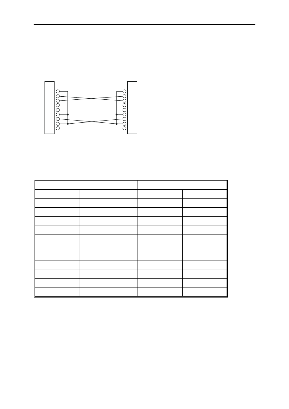
<>: These pins are connected to each other. Additionally to this PIN 1, PIN 6 and PIN
8 have to be connected with a bridge.
PIN
1
2
3
4
5
6
7
8
9
DSUB9-Socket
DSUB9-Socket
PIN
1
2
3
4
5
6
7
8
9
Fig. 3.5: PC data cable DSUB9<>DSUB9
Cabling of a modem elimination cable DSUB9<>DSUB25
DSUB9 socket
DSUB25 socket
Signal PIN
PIN Signal
/RXD 2
<>
2 /TXD
/TXD 3
<>
3 /RXD
GND 5
<>
7 GND
RTS 7
<>
5 CTS
|
6
DSR
|
8
DCD
CTS 8
<>
4 RTS
DCD 1
|
DSR 6
|
Fig. 3.6: PIN designation PC data cable DSUB9<>DSUB25
<>: These pins are connected to each other
short circuits on PIN 1, PIN 6 and PIN 8 on the DSUB9 socket and PIN 5, PIN 6 and
PIN 8 on the DSUB25 socket.