Yaskawa YASNAC PC NC I/O Signal Function Manual User Manual
Page 39
5 - 2
YASNAC PCNC I/O Signal Function Manual Chapter 5: Coordinate Systems
5.1 Reference Point Return Control Input/Output Signals
These are input/output signals used for the return function which positions the axes at the pre-
determined reference point when the CNC power is turned ON.
(1) Reference Point Return Methods
For the execution of the reference point return, the following methods are provided:
Grid type
High-speed type
(a) Grid type Reference Point Return
With this method, the reference point is determined by the zero-point pulse of the position
encoder (1 pulse/turn).
After turning the CNC power ON, close the ZRN input with the manual jog operation
mode or rapid feed mode, and move the axis in the reference point return direction.
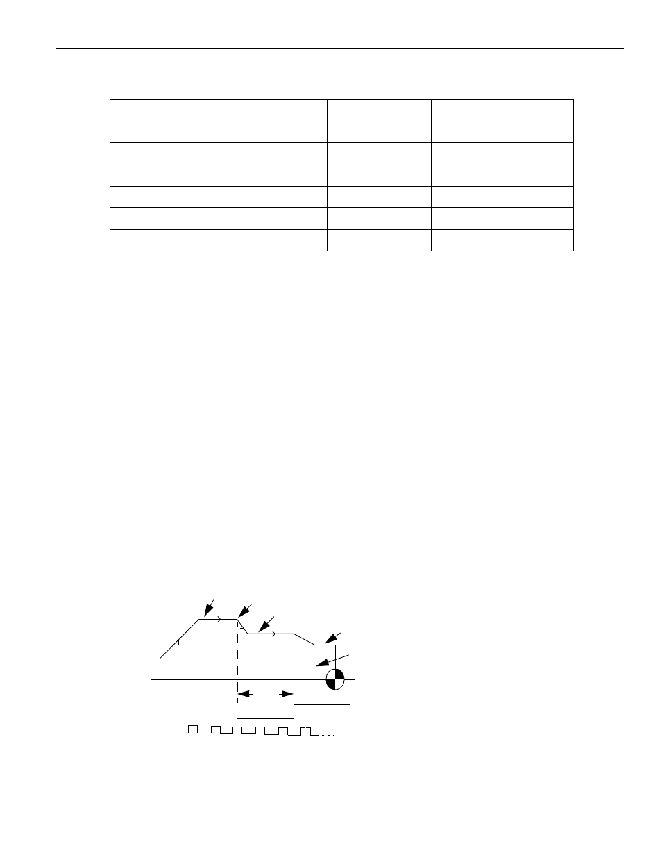
Then, the reference point return operation is executed in the sequence as shown in Fig.
5.1.
The G28 command in automatic mode is executed in the same manner as above.
Fig. 5.1 Reference Point Return Sequence (Grid type)
Reference Point Return Input Signal
ZRN
#30070
Reference Point Return Deceleration LS
*DCX to *DC5
#30730 to #30734
Second Reference Point Return Input Signal
ZRN2
#30071
At the Reference Point Output Signal
ZPX TO ZP5
#36300 TO #36304
At the Second Reference Point Output Signal
2ZPX to 2ZP5
#36310 to #36314
At the Third Reference Point Output Signal
3ZPX to 3ZP5
#36320 to #36324
At the Fourth Reference Point Output Signal
4ZPX to 4ZP5
#36330 to #36334
Feedrate Rapid traverse (pm2801 to pm2805)
Decel. point
Approach speed (pm2521 to pm2525)
Creep speed (pm 2531 to pm2535)
Moved distance (pm4451 to pm 4455)
Feedrate sequence
(*DECX, *DECY, *DECZ, *DEC4, *DEC5)
Feedrate LS signal
Zero-point pulse
Dog
width