Caution – Yaskawa YASNAC PC NC I/O Signal Function Manual User Manual
Page 47
6 - 6
YASNAC PCNC I/O Signal Function Manual Chapter 6: Operation Support Functions
5.
If a manual operation mode input signal is given while a tapping cycle is executed in auto-
matic mode, the automatic mode is maintained until thread cutting is completed.
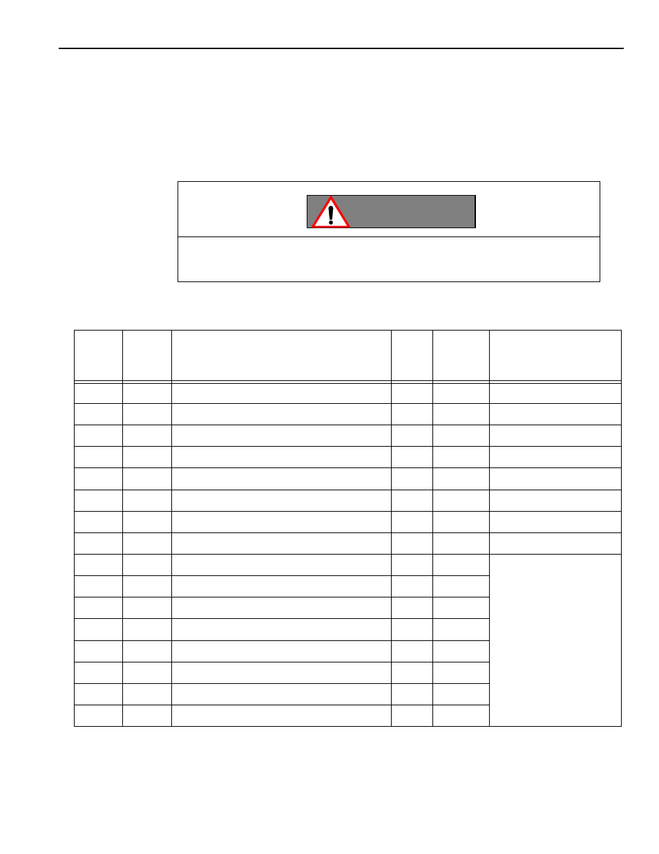
(4) System Number Switch Monitor Output Signals
The status (0 to F) of the rotary switch “SW2” on the JCP01 board is output by the system
number switch monitor output signal.
System Number Switch Functions Table
Note: Rotary switch settings 8 through F are for the Yaskawa Mode.
#35023
to
#35020
Rotary
Switch
Setting
Function
ROM
Check
Watchdog
Remarks
0000
0
Normal operation
á
á
With ladder debug function
0001
1
End user parameter change mode
á
á
With ladder debug function
0010
2
Standard/option parameter change mode
á
á
With ladder debug function
0011
3
Not used
0100
4
Ladder program exit mode
á
á
With ladder debug function
0101
5
Not Used
0110
6
Not Used
0111
7
Not Used
1000
8
On-line maintenance mode
These positions must not
be selected since they call
the modes on for Yaskawa.
1001
9
Software debug mode 1
á
1010
A
Software debug mode 2
1011
B
Running test mode
á
á
1100
C
PCB test mode
á
1101
D
Not used
1110
E
Operation to check contents in memory
1111
F
Total make made (for maintenance)
CAUTION
The rotary switch SW2 defines the CNC operation and must not be changed
without consulting your Yaskawa representative, or the machine tool builder.