Yaskawa DeviceNet Option Card CM05x User Manual
Page 22
Setup and Installation 3-7
1.
Remove power from the Drive and wait for the charge lamp to be completely extinguished. Wait at least
five additional minutes for the Drive to be completely discharged. Measure the DC BUS voltage and
verify that it is at a safe level.
2. Remove the Drive’s operator keypad by depressing the tab on the right side of the keypad and then
pulling it out.
3. Remove the Drive’s front cover(s) until the entire control card is exposed. The number of cover(s) and the
removal procedure varies by drive series and capacity. Consult the Drive’s technical manual for details.
Remove the operator keypad by depressing the tab on the right side of the keypad and then pulling it
out.
4. Remove the option board hold-down clip on the left side of the Drive case by carefully compressing the
top and bottom until it becomes free of its holder and then pulling it out.
5. Align the J1 connector on the back of the DeviceNet Option Board with its mating 2CN connector on the
front of the Drive control card. Align the three standoffs on the front of the Drive control board with the
three holes on the right side of the DeviceNet Option. Press the DeviceNet option firmly onto the Drive
2CN connector and standoffs until the 2CN connector is fully seated and the Drive standoffs have locked
into their appropriate holes.
6. Connect the option ground wire to ground terminal on the F7, G7, or P7 Drive terminal boards.
7. Connect the DeviceNet cable to the DeviceNet terminal on the Option Board according to the wire name
on the DeviceNet Option Board.
8. The DIP switches (S1) located on the front of the DeviceNet Option Board should be properly configured.
See “Option Board Setup” earlier in this chapter.
9. Replace the Drive front cover and Digital Operator.
10.
Apply power to the Drive and verify that the diagnostic LEDs on the front of the DeviceNet Option Board
perform the following LED check and are in their correct state.
MS LED ON Green for 0.25 seconds.
MS LED ON Red for 0.25 seconds.
MS LED ON Green for 0.25 seconds.
NS LED ON Green for 0.25 seconds.
NS LED ON Red for 0.25 seconds.
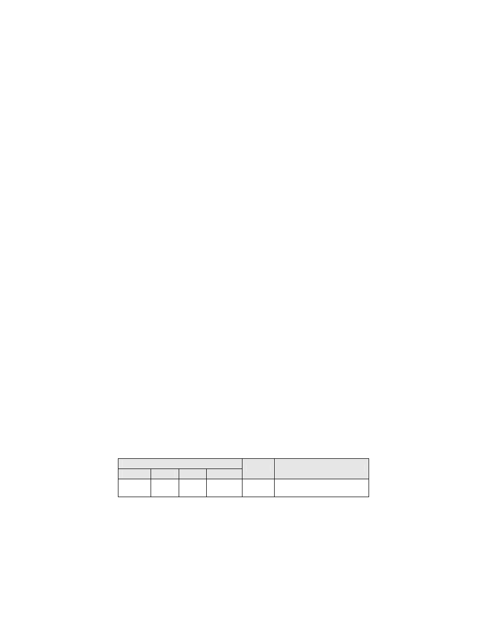
LED Display
PWR
MS
NS
WD
Content
Cause
Solid
Green
Solid
Green
Solid
Green
Flashing
Green
Normal Normal
communication