Amprobe – Amprobe Multitest-2000 Continuity-Tester User Manual
Page 166
AMPROBE
MULTITEST2000
• Phase harmonic currents are reflected on the primary circuit and continue back to the
power source. This can cause distortion of the voltage wave so that any power factor
correction capacitors on the line can be easily overloaded.
The 5
th
and the 11
th
harmonic contrast the current flow through the motors making its
operation harder and shortening their average life.
In general, the higher the ordinal harmonic number, the smaller its energy is and therefore
the impact it will have on the devices (except for transformers).
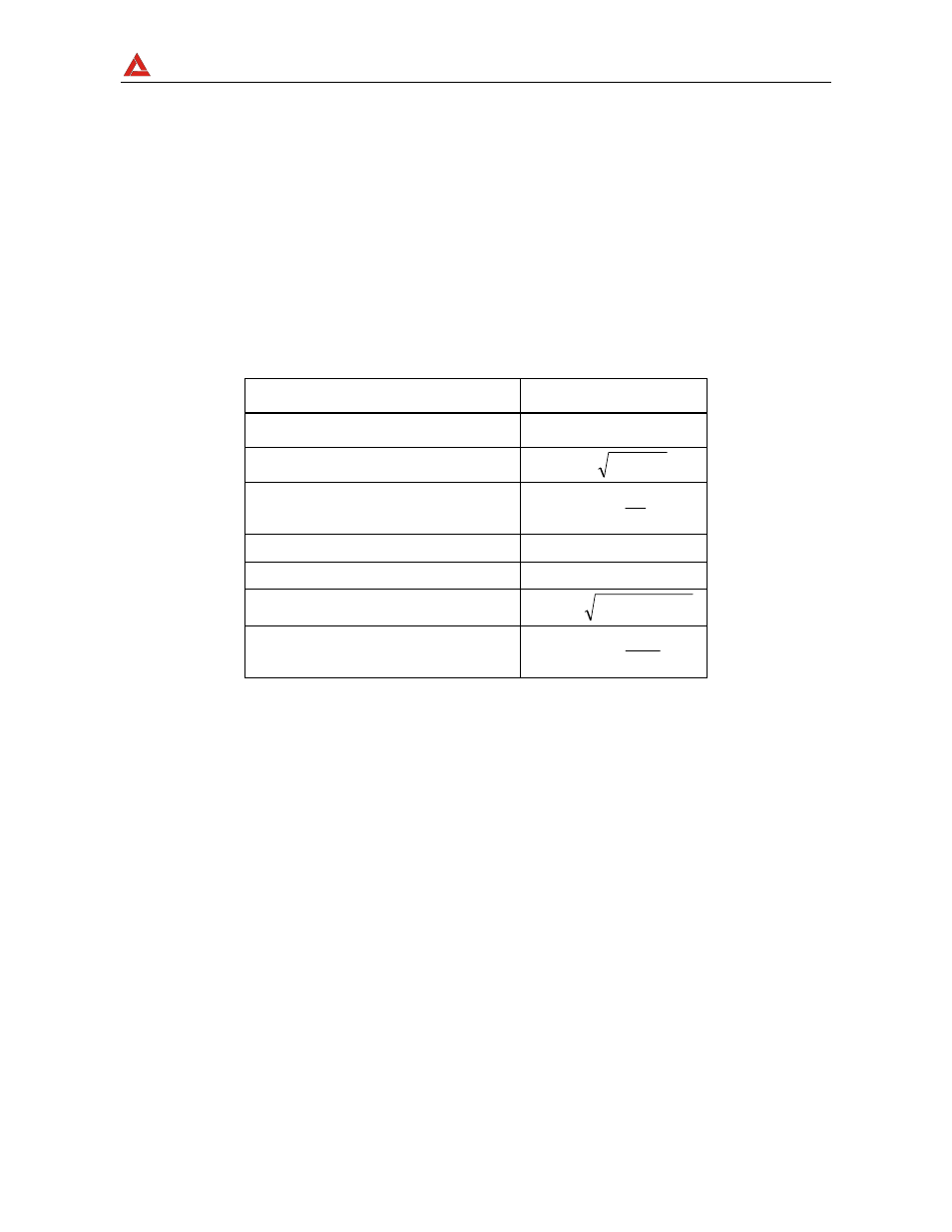
16.7. POWER AND POWER FACTOR DEFINITION
In a standard electric installation powered by three sine voltages the following is defined:
Phase Active Power:
(n=1,2,3)
)
cos(
I
V
P
n
n
nN
n
ϕ
⋅
⋅
=
Phase Apparent Power:
(n=1,2,3)
n
nN
n
I
V
S
⋅
=
Phase Reactive Power:
(n=1,2,3)
2
2
n
n
n
P
S
Q
−
=
Phase Power Factor:
(n=1,2,3)
n
n
n
F
S
P
P
=
Total Active Power:
3
2
1
P
P
P
P
TOT
+
+
=
Total Reactive Power:
3
2
1
Q
Q
Q
Q
TOT
+
+
=
Total Apparent Power:
2
2
TOT
TOT
TOT
Q
P
S
+
=
Total Power Factor:
TOT
TOT
TOT
F
S
P
P
=
where:
V
nN
=
RMS value of voltage between phase n and Neutral.
I
n
=
RMS value of n phase current.