Mt 2000, Amprobe – Amprobe Multitest-2000 Continuity-Tester User Manual
Page 17
AMPROBE
MULTITEST2000
4.1. DISPLAY
DESCRIPTION
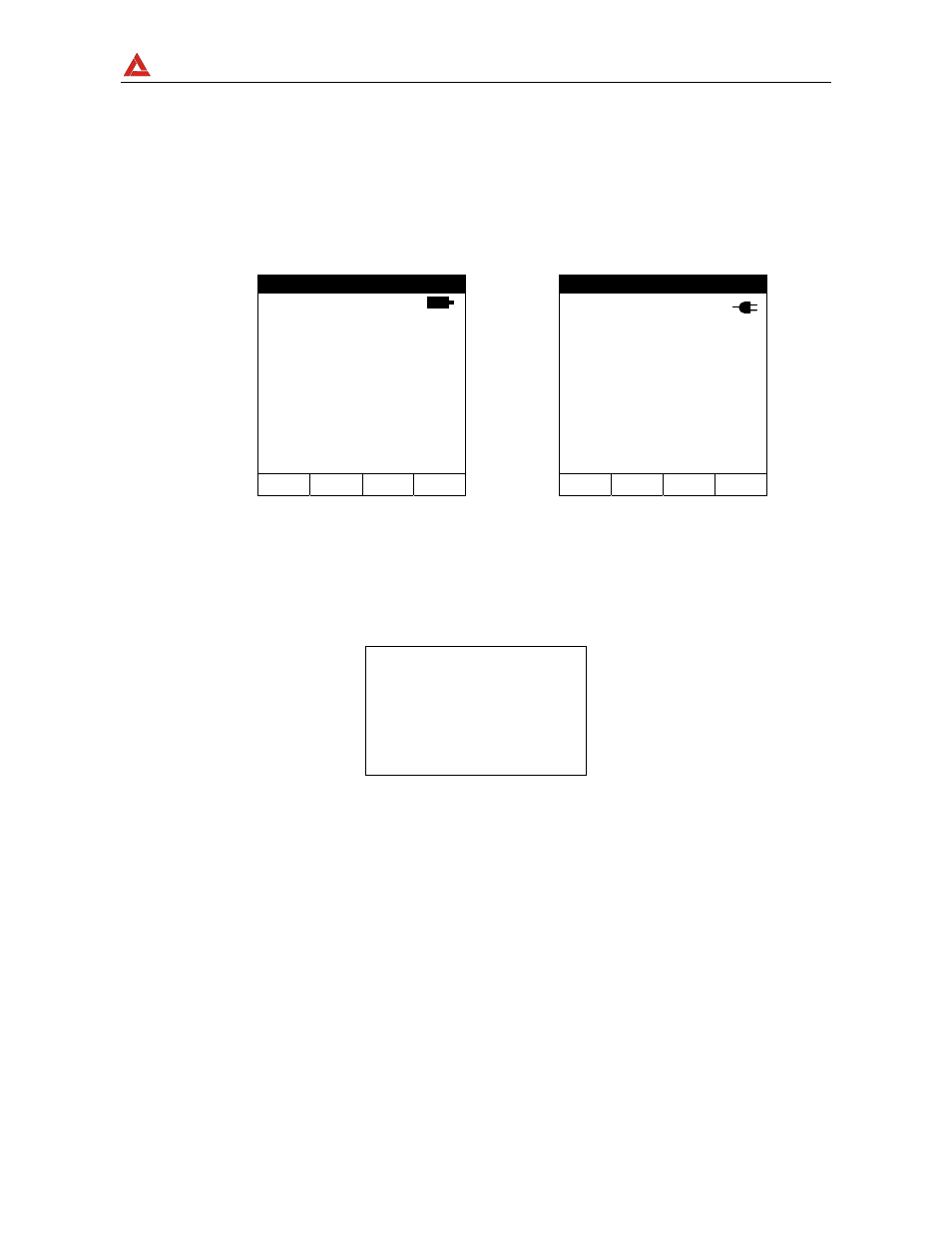
The display is a graphic module with a resolution of128 x 128 pixels
The first line of the display shows date and time. If not correct, you can set the exact ones
according to the procedure described at paragraph 5.2.
On the top right corner of the display you can always see the battery indicator and, if the
external power supply adapter (optional code A0050) is connected, the corresponding
symbol.
LOW
Ω 05.06.01
27.09.00 17:35:12
----
Ω
R+ R-
----
Ω ----Ω
---mA ---mA
AUTO 0.11
Ω
SINGLE PHASE
VOLTAGE
V1 = 230.2 V
Vpk1 = 325.5 V
ThdV = 0.0 %
freq = 50.0 Hz
FUNC
CAL
HARM
WAVE
These symbols will be omitted in the following illustrations.
4.2. INITIAL
SCREEN
When turning on the instrument by pressing ON/OFF, this screen will appear for a few
seconds:
MT 2000
AMPROBE
SN:00000000 V: X.XX