Amprobe – Amprobe Multitest-2000 Continuity-Tester User Manual
Page 95
AMPROBE
MULTITEST2000
8.4.3. "HARM"
mode
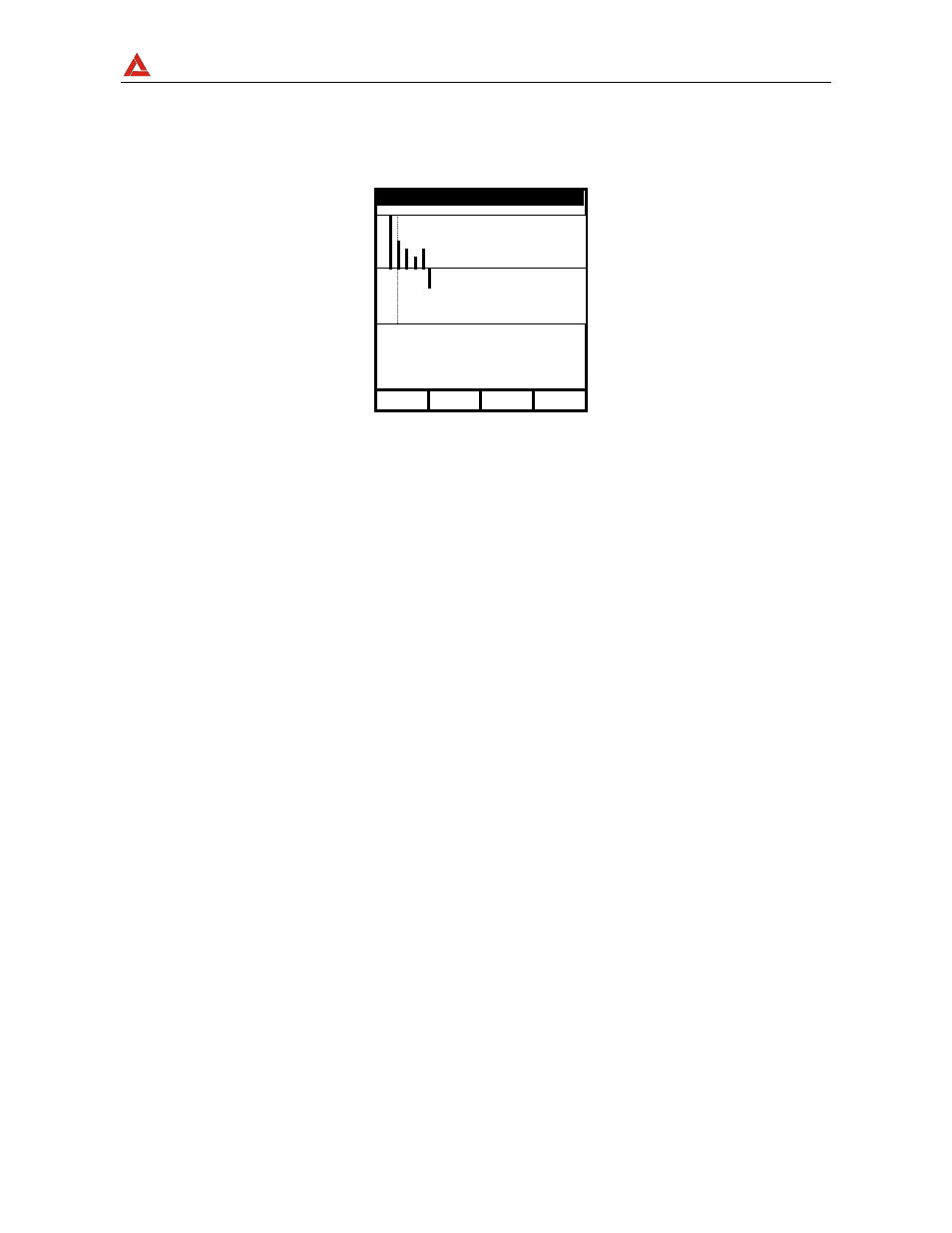
Selecting the HARM mode the screen below will be displayed according to the settings
made as per paragraph 8.1. The screen show the harmonics (see paragraph 16.6) of the
voltage.
Example of screen
The symbols used are described in Tab. 1.
For eventual messages displayed see appendix 1 – MESSAGES DISPLAYED.
The displayed histograms represent the harmonic content of the voltage under test. The
value of the first harmonic h01 (fundamental at 50Hz) is not represented in scale along
with the other harmonics in order to maximize the display of the latter. In case both voltage
and current are connected to the instrument inputs, eventual negative values of the
harmonics (therefore represented under the horizontal axis), indicate that such voltage
harmonics are “generated” by the load.
Following keys are enabled:
27.09.00 17:35:12
V1 = 230.2 V
h03 = 10.2 V
h03 = 4.3 %
ThdV = 11.0 %
h49
←
→