Setting jumpers – ProSoft Technology MVI56E-MCMR User Manual
Page 17
MVI56E-MCMR ♦ ControlLogix Platform
Start Here
Modbus Communication Module with Reduced Data Block
User Manual
ProSoft Technology, Inc.
Page 17 of 225
May 13, 2014
1.5
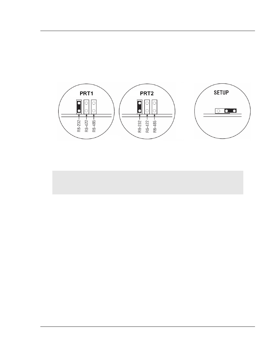
Setting Jumpers
There are three jumpers located at the bottom of the module. The first two
jumpers (P1 and P2) set the serial communication mode: RS-232, RS-422 or RS-
485.
The following illustration shows the MVI56E-MCMR jumper configuration, with
the Setup Jumper OFF.
The Setup Jumper acts as "write protection" for the module’s firmware. In "write
protected" mode, the Setup
pins are not connected, and the module’s firmware
cannot be overwritten. The module is shipped with the Setup jumper OFF. If you
need to update the firmware, apply the Setup jumper to both pins.
Note: If you are installing the module in a remote rack, you may prefer to leave the Setup pins
jumpered. That way, you can update the module’s firmware without requiring physical access to
the module.