ProSoft Technology MVI56E-MCMR User Manual
Page 77
MVI56E-MCMR ♦ ControlLogix Platform
Configuring the MVI56E-MCMR Module
Modbus Communication Module with Reduced Data Block
User Manual
ProSoft Technology, Inc.
Page 77 of 225
May 13, 2014
Write Floats to Slave Device
To issue a Write command to Floating-Point addresses, use the configuration in
the following table. The table describes the Modbus Map for the slave device.
Value
Description
Type
40261
KW
Demand (power)
Float. upper 16 bits
40263
VAR
Reactive Power
Float. upper 16 bits
40265
VA
Apparent Power
Float. upper 16 bits
40267
Power Factor
Float. upper 16 bits
40269
VOLTS
Voltage, line to line
Float. upper 16 bits
40271
VOLTS
Voltage, line to neutral
Float. upper 16 bits
40273
AMPS
Current
Float. upper 16 bits
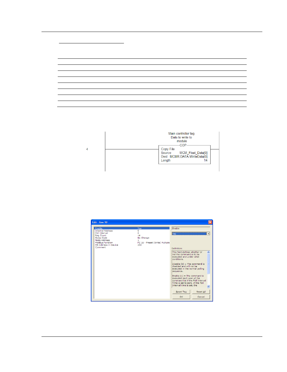
You must use a COP
statement to copy the data from floating-point data tags
within the ControlLogix processor, into the MCMR.DATA.W
RITE
D
ATA
array used
by the MVI56E-MCMR module. Below is an example.
The length of this COP statement must now be 14. This will COP as many of the
MCM_F
LOAT
_D
ATA
values required to occupy the MCMR.DATA.W
RITE
D
ATA
array for a length of 14. This will take 7 registers, MCM_F
LOAT
_D
ATA
[0]
TO
[6],
and place that data into MCMR.DATA.W
RITE
D
ATA
[0]
TO
[13].
You must configure the command to write all 7 floats (14 Modbus addresses) as
follows.
The above command will take the data from MCMR.DATA.W
RITE
D
ATA
[0]
TO
[13]
and write this information to Modbus Slave Device Address 1 at data addresses
40261 to 40274.