ProSoft Technology MVI56E-MCMR User Manual
Page 203
MVI56E-MCMR ♦ ControlLogix Platform
Reference
Modbus Communication Module with Reduced Data Block
User Manual
ProSoft Technology, Inc.
Page 203 of 225
May 13, 2014
6.8
Using the Sample Program - RSLogix 5000 Version 15 and earlier
he sample program included with your MVI56E-MCMR module contains
predefined controller tags, configuration information, data types, and ladder logic
that allow the module to communicate between the ControlLogix processor and a
network of MCMR devices. For most applications, the sample program will work
without modification.
6.8.1 Adding the Sample Ladder to an Existing Application
1 Copy the Controller Tags (page 118) from the sample program.
2 Copy the User-Defined Data Types (page 118) from the sample program.
3 Copy the Ladder Rungs from the sample program.
4 Save and Download (page 43) the new application to the controller and place
the processor in run mode.
If all the configuration parameters are set correctly and the module is attached to
the Modbus network, the module's Application LED (APP LED) should remain off
and the backplane activity LED (BP ACT) should blink rapidly. If you encounter
errors, refer to Diagnostics and Troubleshooting (page 122, page 130).
6.8.2 Add the Module to the Project
Important: The following steps describe how to install and configure the MVI56E-MCMR module
with RSLogix 5000 version 15 or older. If you are using RSLogix 5000 version 16, please refer to
Sample Add-On Instruction Import Procedure.
Note: The RSLogix software must be in "offline" mode to add the module to a project.
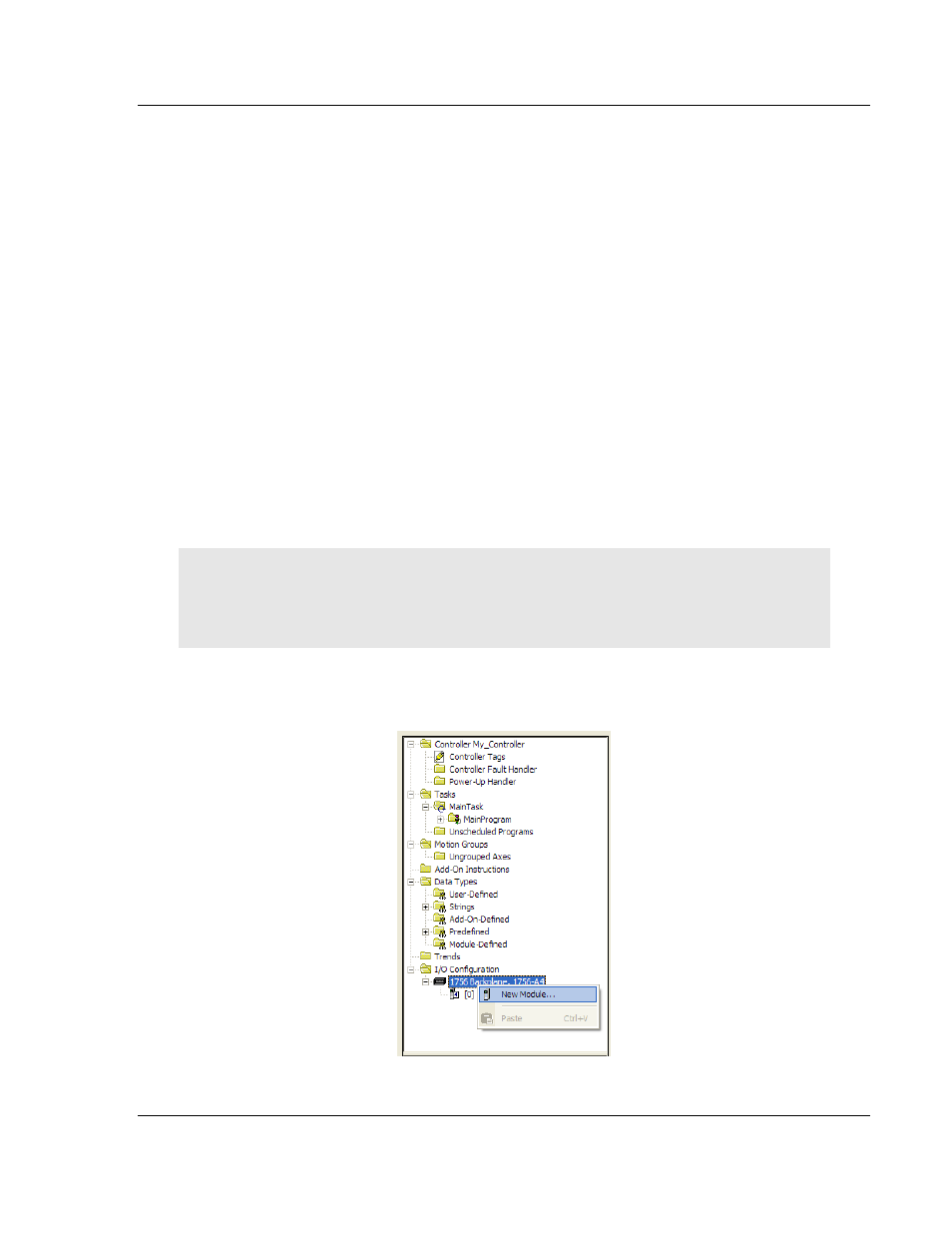
1 In the C
ONTROLLER
O
RGANIZATION
window, select I/O
C
ONFIGURATION
, and
then click the right mouse button to open a shortcut menu. On the shortcut
menu, choose N
EW
M
ODULE
.