ProSoft Technology MVI56E-MCMR User Manual
Page 66
Configuring the MVI56E-MCMR Module
MVI56E-MCMR ♦ ControlLogix Platform
User Manual
Modbus Communication Module with Reduced Data Block
Page 66 of 225
ProSoft Technology, Inc.
May 13, 2014
Parameter
Description
Enable = YES
The module will send the command every time it goes through the
command list.
Internal Address = 1000
Begins placing the data read from the slave device into the module at
address 1000. Internal Address 1000 of the module memory will be
copied into the tag MCMR.DATA.R
EAD
D
ATA
[0], assuming
MCMR.CONFIG.ReadStartReg = 1000.
Reg Count = 10
Read 10 consecutive registers from the Slave device.
Node Address = 1
Issues the Modbus command to Modbus Slave Device Address 1.
Modbus Function =3
Issues Modbus Function Code 3 to Read Holding Registers.
MB Address in Device = 0
Using Function Code 3, MB Address in Device of 0 will read Holding
Register address 40001 (or 400001, if using 6-digit addressing)
With a count of 10, this command reads 40001 to 40010 (400001 to
400010).
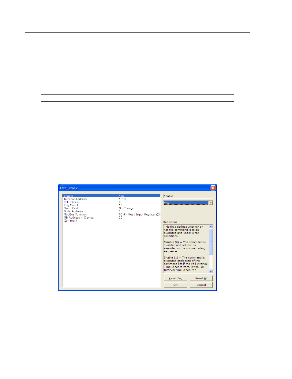
Read Input Registers 3xxxxx (Modbus Function Code 4)
Like the 4x holding registers, 3x input registers are used for reading analog
values that are 16-bit register values. You can also use these registers to store
floating-point data (page 74). Unlike the 4x registers, 3x registers are Read Only.
The following illustration shows a sample command to read Modbus addresses
30021 to 30030 of Modbus Slave Device Address 1.