Configuration as a modbus slave – ProSoft Technology MVI56E-MCMR User Manual
Page 81
MVI56E-MCMR ♦ ControlLogix Platform
Configuring the MVI56E-MCMR Module
Modbus Communication Module with Reduced Data Block
User Manual
ProSoft Technology, Inc.
Page 81 of 225
May 13, 2014
2.4
Configuration as a Modbus Slave
2.4.1 Overview
When configuring the module as a slave, you will be providing a Modbus Memory
Map to the person who is programming the Master side of the communications.
Note: If you are using the Sample Ladder Logic, the transfer of data is already done.
Information that is to be read by the Modbus Master device will be placed in the
MCMR.DATA.W
RITE
D
ATA
array as this will be pushed out to the module so that
values from the ControlLogix processor can be read by the Modbus Master.
Information that must be written to the ControlLogix processor from the Modbus
Master device will be placed into the MCMR.DATA.R
EAD
D
ATA
array.
To configure module as a Modbus Slave, you must determine how much data
you must transfer to and from the module, to the Modbus Master.
The sample ladder file is configured to transfer 600 16-bit registers in each
direction. If more than that is required, please see Applications Requiring More
Than 600 Registers of ReadData or WriteData.
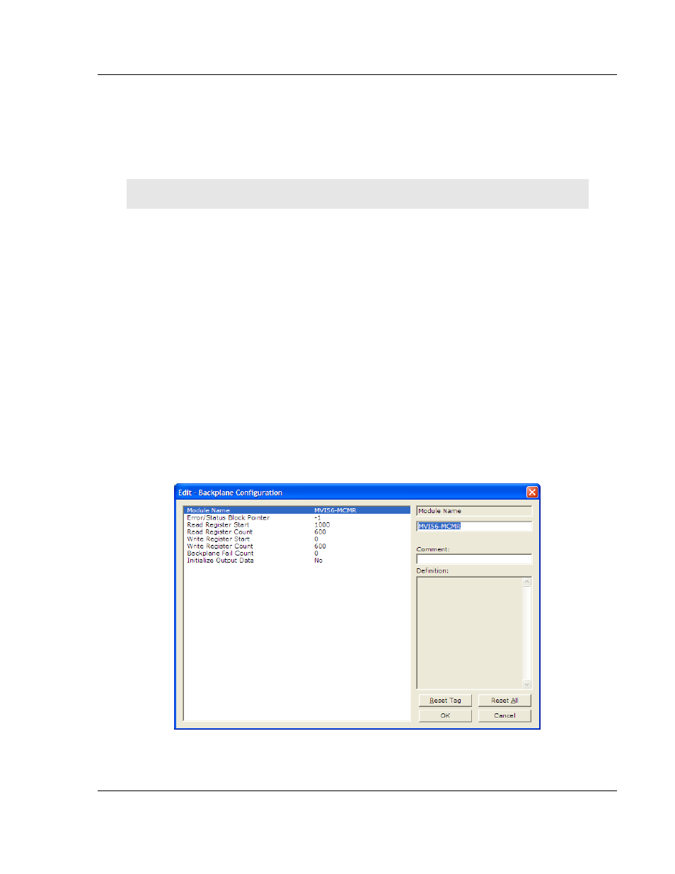
2.4.2 Configuration File Settings
To configure Modbus slave mode, use the B
ACKPLANE
C
ONFIGURATION
settings.
This section specifies which of the MVI56E-MCMR module's 5000 registers of
memory to send from the ControlLogix processor to the MVI56E-MCMR module
(WriteData) and which registers to send from the MVI56E-MCMR module to the
ControlLogix processor (ReadData).