ProSoft Technology MVI56E-MCMR User Manual
Page 84
Configuring the MVI56E-MCMR Module
MVI56E-MCMR ♦ ControlLogix Platform
User Manual
Modbus Communication Module with Reduced Data Block
Page 84 of 225
ProSoft Technology, Inc.
May 13, 2014
Although these are valid addresses, they will not work in the application. The
Master must issue a Write command to the addresses that correspond to the
R
EAD
D
ATA
array. For Modbus addresses 3x, these are considered Input
registers, and a Modbus Master does not have a function code for this type of
data.
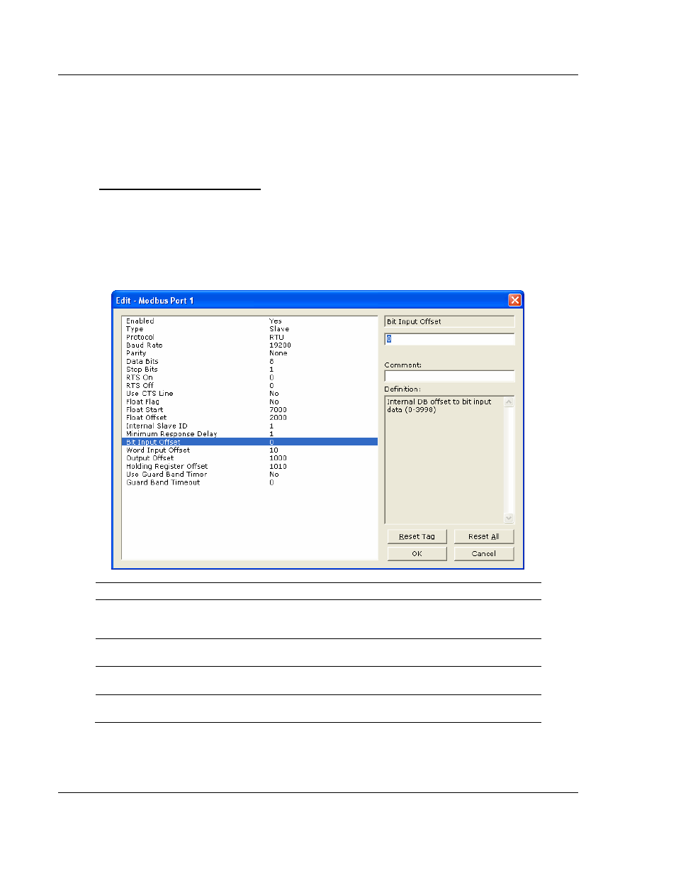
Customizing the Memory Map
In some cases, the above memory map will not work for the application.
Sometimes a Master must read bits starting at address 0001, and must also read
a register starting at 40001. With the memory map in this example (page 83), this
is not possible, as W
RITE
D
ATA
[0]
is seen as both 0001 to 0016, and 40001. To
accommodate this, you can customize the starting location within the module for
each device using the parameters shown below.
Parameter
Value
Description
Bit Input Offset
0
Defines the starting address within the module for 1x
Modbus addressing. A value of 0 sets 10001 to 10016 as
address 0 in the MVI56E-MCMR module.
Word Input Offset
10
Defines the starting address within the module memory
for 3x registers.
Output Offset
1000
Defines the starting address within the module for 0x
coils.
Holding Register Offset
1010
Defines the starting address within the module for 4x
addressing.