ProSoft Technology PTQ-AFC User Manual
Page 168
Backplane Communication
PTQ-AFC ♦ Modicon Quantum Platform
User Manual
Liquid and Gas Flow Computer for Hydrocarbon Products
Page 168 of 259
ProSoft Technology, Inc.
June 23, 2011
9.1
Site PLC Configuration
The following blocks of registers can be associated with a Quantum memory
location. The module will automatically read and write data from/to the Quantum
processor without the need of any processor logic.
Block Description
Block Size
Required
Supervisory output from PLC to AFC
52 Yes
Supervisory input from AFC to PLC
50
No (but recommended)
Wallclock
6 Yes
Modbus Gateway
129 No
Modbus Pass-Thru
130 No
Modbus Master
130 No
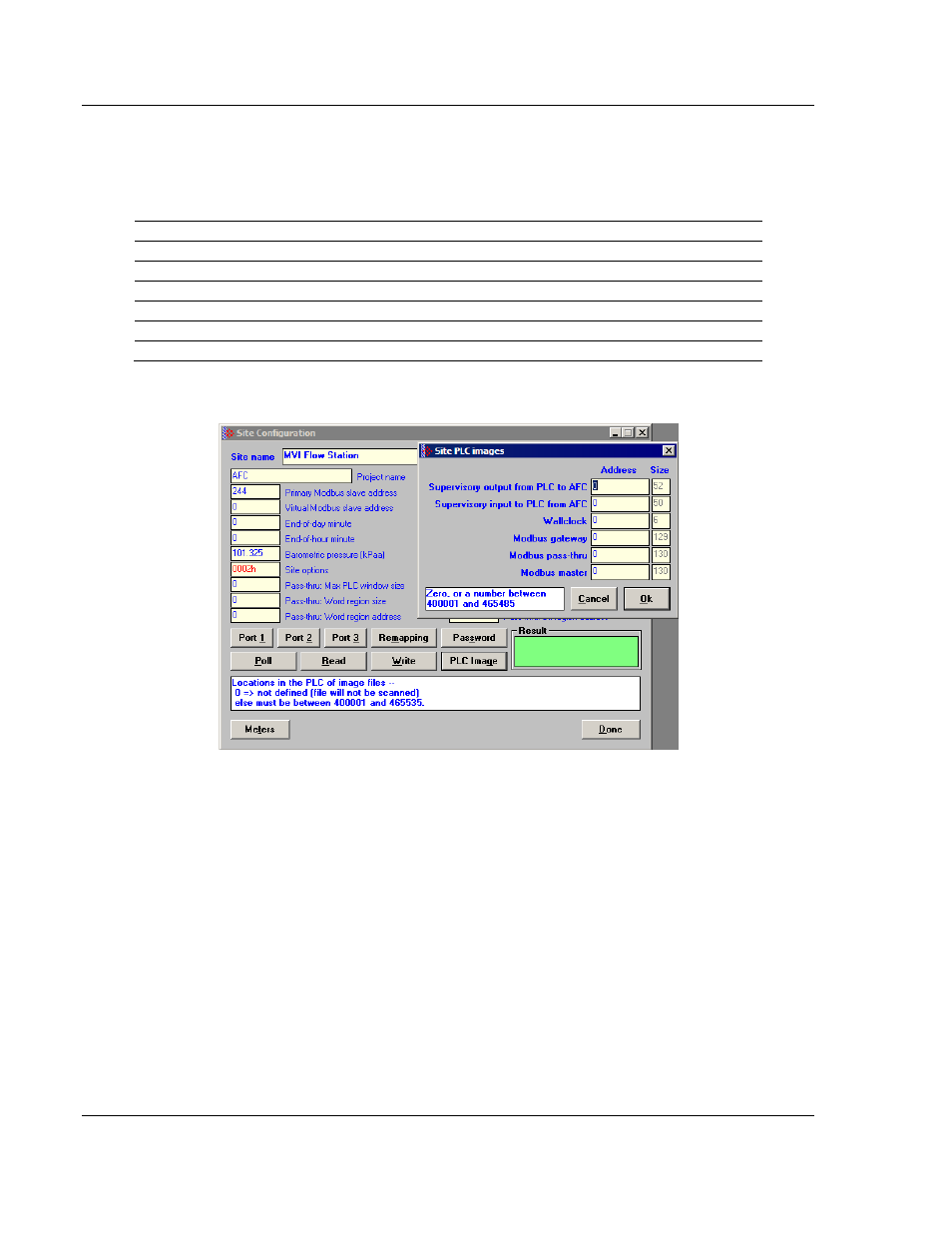
You can configure the Site PLC blocks through the AFC Manager (Site
Configuration / PLC Image
) as shown below:
An image address of zero means that the block is not defined; it will not be
accessed and need not be allocated in the processor. Otherwise the image
address must be located within the 4x register bank defined to the processor.
Make sure that all defined blocks are assigned to separate locations and do not
overlap; do not share Modbus addresses among blocks.
In the following layouts, determine the Modbus address of a point by adding the
point’s offset to the configured image address.
The following table shows the various types of registers listed throughout the
following pages: