External interfaces, Clock and reset interface, Avalon-st data slave interface – Altera DDR SDRAM High-Performance Controllers and ALTMEMPHY IP User Manual
Page 103: Controller-phy interface, External interfaces –9

Chapter 6: Functional Description—High-Performance Controller II
6–9
External Interfaces
June 2011
Altera Corporation
External Memory Interface Handbook Volume 3
Section I. DDR and DDR2 SDRAM Controllers with ALTMEMPHY IP User Guide
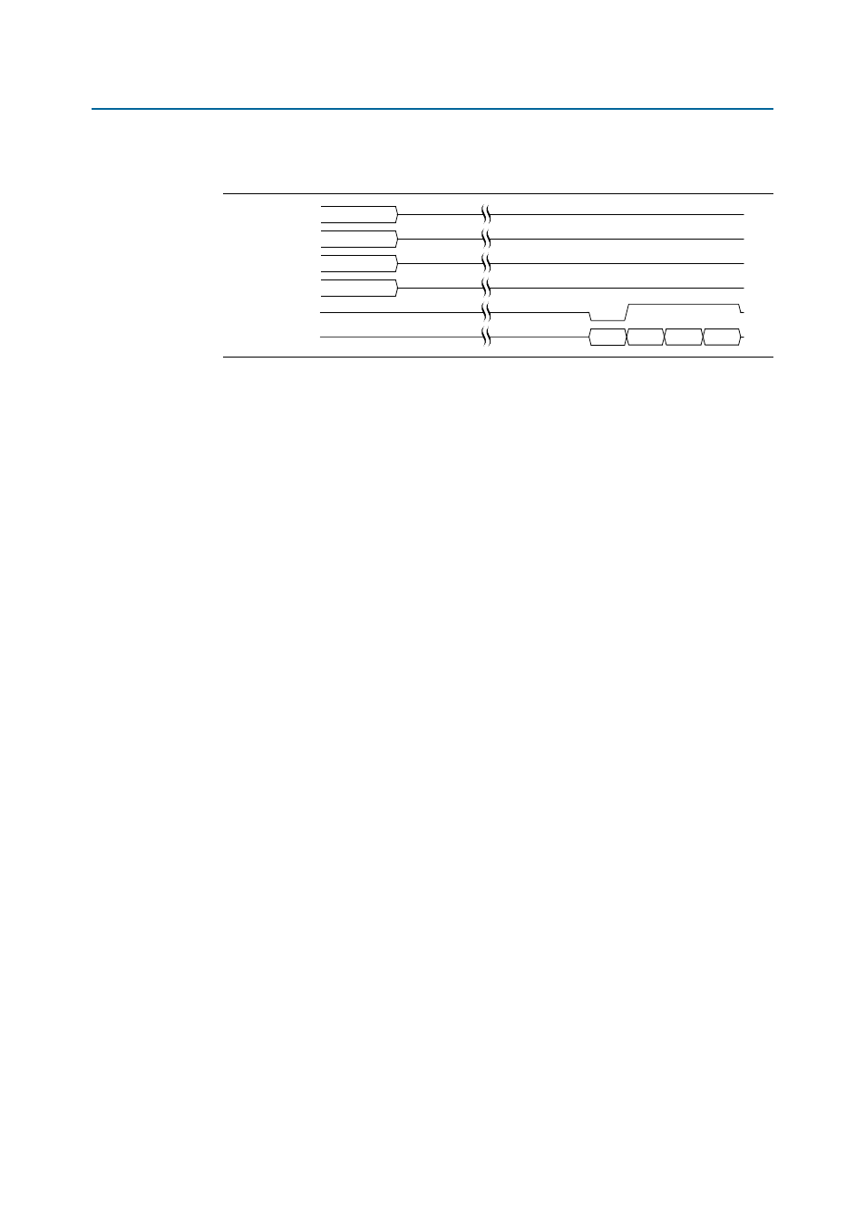
Figure 6–5
shows a partial burst operation for the controller.
External Interfaces
This section discusses the interfaces between the controller and other external
memory interface components.
Clock and Reset Interface
The clock and reset interface is part of the AFI interface.
The controller can have up to two clock domains, which are synchronous to each
other. The controller operates with a single clock domain when there is no integrated
half-rate bridge, and with two-clock domains when there is an integrated half-rate
bridge. The clocks are provided by UniPHY.
The main controller clock is afi_clk, and the optional half-rate controller clock is
afi_half_clk
. The main and half-rate clocks must be synchronous and have a 2:1
frequency ratio.
Avalon-ST Data Slave Interface
The Avalon-ST data slave interface consists of the following Avalon-ST channels,
which together form a single data slave:
■
The command channel, which serves as command and address for both read and
write operations.
■
The write data channel, which carries write data.
■
The read data channel, which carries read data.
■
The write response channel, which is an AXI protocol.
f
For information about the Avalon interface, refer to
Controller-PHY Interface
The interface between the controller and the PHY is part of the AFI interface.
The controller assumes that the PHY performs all necessary calibration processes
without any interaction with the controller.
For more information about AFI signals, refer to
Figure 6–5. Partial Burst for Controller
local_address
local_size
local_be
local_wdata
mem_dm
mem_dq
0
1
X1
01234567
67
45
23
01