Altera DDR SDRAM High-Performance Controllers and ALTMEMPHY IP User Manual
Page 76
5–30
Chapter 5: Functional Description—ALTMEMPHY
ALTMEMPHY Signals
External Memory Interface Handbook Volume 3
June 2011
Altera Corporation
Section I. DDR and DDR2 SDRAM Controllers with ALTMEMPHY IP User Guide
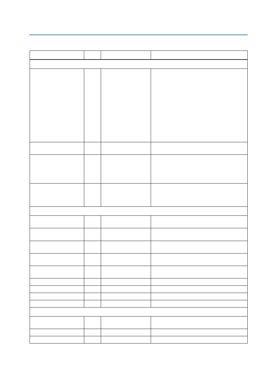
Read Data Interface
ctl_doing_rd
Input
MEM_IF_DQS_WIDTH
×
DWIDTH_RATIO
/ 2
Doing read input. Indicates that the DDR or DDR2
SDRAM controller is currently performing a read
operation.
The controller generates ctl_doing_rd to the
ALTMEMPHY megafunction. The ctl_doing_rd
signal is asserted for one phy_clk cycle for every
read command it issues. If there are two read
commands, ctl_doing_rd is asserted for two
phy_clk
cycles. The ctl_doing_rd signal also
enables the capture registers and generates the
ctl_mem_rdata_valid
signal. The ctl_doing_rd
signal should be issued at the same time the read
command is sent to the ALTMEMPHY megafunction.
ctl_rdata
Output
DWIDTH_RATIO
×
MEM_IF_DWIDTH
Read data from the PHY to the controller.
ctl_rdata_valid
Output
DWIDTH_RATIO
/2
Read data valid indicating valid read data on
ctl_rdata
. This signal is two-bits wide (as only
half-rate or DWIDTH_RATIO = 4 is supported) to allow
controllers to issue reads and writes that are aligned
to either the half-cycle of the half-rate clock.
ctl_rlat
Output
READ_LAT_WIDTH
Contains the number of clock cycles between the
assertion of ctl_doing_rd and the return of valid
read data (ctl_rdata). This is unused by the Altera
high-performance controllers do not use ctl_rlat.
Address and Command Interface
ctl_addr
Input
MEM_IF_ROWADDR_WIDTH
× DWIDTH_RATIO / 2
Row address from the controller.
ctl_ba
Input
MEM_IF_BANKADDR_WIDT
H
× DWIDTH_RATIO / 2
Bank address from the controller.
ctl_cke
Input
MEM_IF_CS_WIDTH
×
DWIDTH_RATIO
/ 2
Clock enable from the controller.
ctl_cs_n
Input
MEM_IF_CS_WIDTH
×DWIDTH_RATIO / 2
Chip select from the controller.
ctl_odt
Input
MEM_IF_CS_WIDTH
×
DWIDTH_RATIO
/ 2
On-die-termination control from the controller.
ctl_ras_n
Input
DWIDTH_RATIO
/ 2
Row address strobe signal from the controller.
ctl_we_n
Input
DWIDTH_RATIO
/ 2
Write enable.
ctl_cas_n
Input
DWIDTH_RATIO
/ 2
Column address strobe signal from the controller.
ctl_rst_n
Input
DWIDTH_RATIO
/ 2
Reset from the controller.
Calibration Control and Status Interface
ctl_mem_clk_disable
Input
MEM_IF_CLK_PAIR_
COUNT
When asserted, mem_clk and mem_clk_n are
disabled. Not supported for Cyclone III devices.
ctl_cal_success
Output
1
A 1 indicates that calibration was successful.
ctl_cal_fail
Output
1
A 1 indicates that calibration has failed.
Table 5–6. AFI Signals (Part 3 of 4)
Signal Name
Type
Width
(1)
Description