Altera DDR SDRAM High-Performance Controllers and ALTMEMPHY IP User Manual
Page 34
3–8
Chapter 3: Parameter Settings
ALTMEMPHY Parameter Settings
External Memory Interface Handbook Volume 3
June 2011
Altera Corporation
Section I. DDR and DDR2 SDRAM Controllers with ALTMEMPHY IP User Guide
t
DS
10–600
ps
DQ and DM input setup time relative to DQS, which has a
derated value depending on the slew rate of the DQS (for
both DDR and DDR2 SDRAM interfaces) and whether
DQS is single-ended or differential (for DDR2 SDRAM
interfaces). Ensure that you are using the correct number
and that the value entered is referenced to V
REF
(dc), not
V
IH
(ac) min or V
IL
(ac) max. Refer to
Setup and Hold Timing” on page 3–9
for more
information about how to derate this specification.
t
DH
10–600
ps
DQ and DM input hold time relative to DQS, which has a
derated value depending on the slew rate of the DQS (for
both DDR and DDR2 SDRAM interfaces) and whether
DQS is single-ended or differential (for DDR2 SDRAM
interfaces). Ensure that you are using the correct number
and that the value entered is referenced to V
REF
(dc), not
V
IH
(dc) min or V
IL
(dc) max. Refer to
Setup and Hold Timing” on page 3–9
for more
information about how to derate this specification.
t
DSH
0.1–0.5
t
CK
DQS falling edge hold time from CK.
t
DSS
0.1–0.5
t
CK
DQS falling edge to CK setup.
t
IH
100–1000
ps
Address and control input hold time, which has a derated
value depending on the slew rate of the CK and CK#
clocks and the address and command signals. Ensure
that you are using the correct number and that the value
entered is referenced to V
REF
(dc), not V
IH
(dc) min or
V
IL
“Derating Memory Setup and Hold
for more information about how to
derate this specification.
t
IS
100–1000
ps
Address and control input setup time, which has a
derated value depending on the slew rate of the CK and
CK# clocks and the address and command signals.
Ensure that you are using the correct number and that the
value entered is referenced to V
REF
(dc), not V
IH
(ac) min
or V
IL
(ac) max. Refer to
for more information about
how to derate this specification.
t
QHS
100–700
ps
The maximum data hold skew factor.
t
RRD
2.06–64
ns
The activate command to activate time, per device, RAS
to RAS delay timing parameter.
t
FAW
7.69–256
ns
The four-activate window time, per device.
t
RTP
2.06–64
ns
Read to precharge time.
Note to
Table 3–5
:
(1) See the memory device data sheet for the parameter range. Some of the parameters may be listed in a clock cycle (t
CK
) unit. If the MegaWizard
Plug-In Manager requires you to enter the value in a time unit (ps or ns), convert the number by multiplying it with the clock period of your
interface (and not the maximum clock period listed in the memory data sheet).
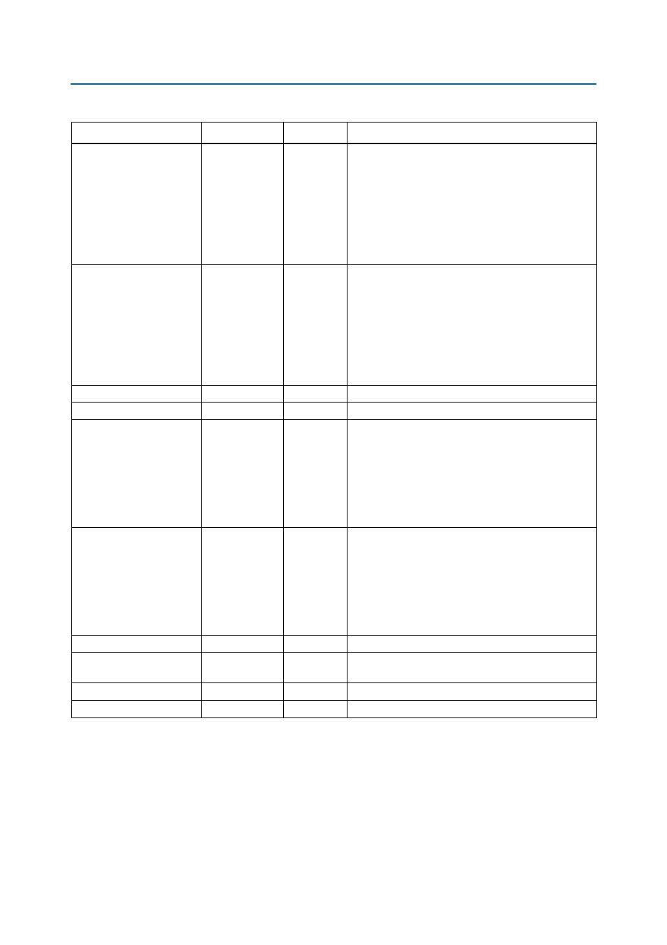
Table 3–5. DDR2 SDRAM Timing Parameter Settings
(Note 1)
(Part 2 of 2)
Parameter Name
Range
Units
Description