Daktronics All Sport 4000 Series User Manual
Page 89
Event Counter
23-5
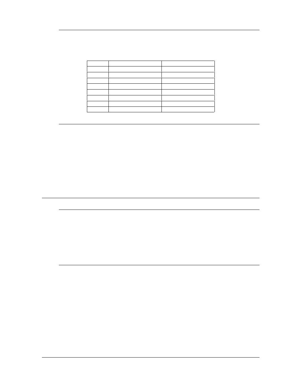
23.4.1 RTD Item Numbers
The console sends out data in a Venus 1500 RTD packet as shown below as data is
changed or a minimum of once every second for code 375, or standard V4600/V7000
RTD for code 376.
Item #
Function
Offset
01
Value x 10,000,000
0
02
Value x 1,000,000
1
03
Value x 100,000
2
04
Value x 10,000
3
05
Value x 1,000
4
06
Value x 100
5
07
Value x 10
6
08
Value x 1
7
23.4.2 External Switch Inputs
A switch-closed input on pins 2 & 5 of switch input terminal block 1 will cause the
console to add the increment value to the total value. A switch-closed input on pins 1 &
6 of switch input terminal block will cause the console to subtract the decrement value
from the total value.
The external switch inputs come into the All Sport on J3. The signal cable used to
connect to these inputs has a 6-pin RJ-11 on one end and a 4-pin terminal block on the
other end. Refer to Appendix A for signal connection drawings.
23.5
System Setup/Operation
23.5.1
Venus 1500 Controlled Products
Install Venus 1500 software and create signs needed by following Venus 1500 manual
(ED-9067) and display manual.
If supplied with a RTD message, copy to the proper directory. The supplied message
is already in the display memory and can be run. To edit or create a new message go
to Section 23.5.2.
23.5.2
Creating an RTD Message
Install Venus 1500 software and create signs needed by following Venus 1500 manual
ED-9067 and the display manual.
Use the Venus 1500 to create a message. Use the following examples to aid in
creating the RTD field within the message.