3 description of the incremental signal display, Check functions bar, Encoder characteristics – HEIDENHAIN PWM 20 User Manual
Page 148
November 2014
Checking incremental encoders
151
6.2.3 Description of the incremental signal display
Check functions
bar
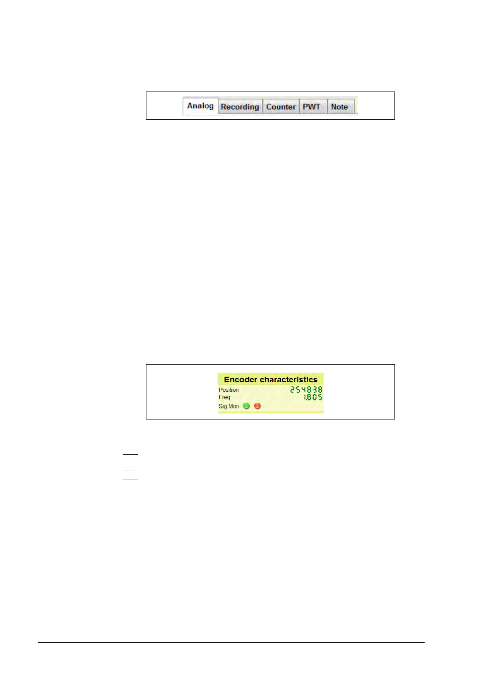
Encoder
characteristics
Analog:
Oscilloscope function
Position and frequency display
Signal monitoring
Bar graphs for parameters of incremental and reference signals
Recording:
Recording of several signal periods for signal analysis
Diagram view of the recorded signal data; comparison of signal
amplitudes, on-to-off ratios and phase shifts
Recorded signal data can be saved and exported; saved files can be
opened.
Counter:
Test of counting function by counter start/stop with ref. mark
PWT:
Phase angle test function for simple testing of analog interfaces
(e.g. 11 µApp and 1 Vpp); bar graphs are displayed to evaluate signal
amplitudes, signal deviation and zero crossovers.
Note:
The software reports problems such as:
Excessive frequencies
The displayed signal detail is too small to calculate the reference mark,
etc.
A yellow Attention symbol is displayed to the right of the Note button.
Position:
Bidirectional counter (counting of signal periods)
Frequency:
Current input frequency
Signal
monitoring:
"Left" LED =
Concurrent signal monitoring (red color only as long as
an error is present)"
Right“ LED =
Signal monitoring is logged (display permanently red,
if an error was detected within the measuring range)