HEIDENHAIN PWM 20 User Manual
Page 32
November 2014
Software description
33
Power-on sequence for feed-through mode
Absolute interfaces (EnDat, Fanuc, ...)
1. Switch on the PWM 20.
2. Start the ATS software.
3. Set the checkmark "Use power supply from subsequent electronics
(= feed-through mode).
4. Connect the absolute encoder by entering its ID (the ID is mandatory!)
5. Switch on the subsequent electronics.
Incremental interfaces (1 Vpp, 11 µApp, ...)
1. Switch on the PWM 20.
2. Start the ATS software.
3. Set the checkmark "Use power supply from subsequent electronics
(= feed-through mode).
4. Connect the incremental encoder by entering its ID or manually by
selecting the interface.
5. Switch on the subsequent electronics.
Encoder output
The encoder input X1 of the PWM 20 is electrically connected with the encoder output X2.
The signals and the pin layout at the output correspond to the respective signals at the input.
DANGER
There is no metallic isolation of the signals.
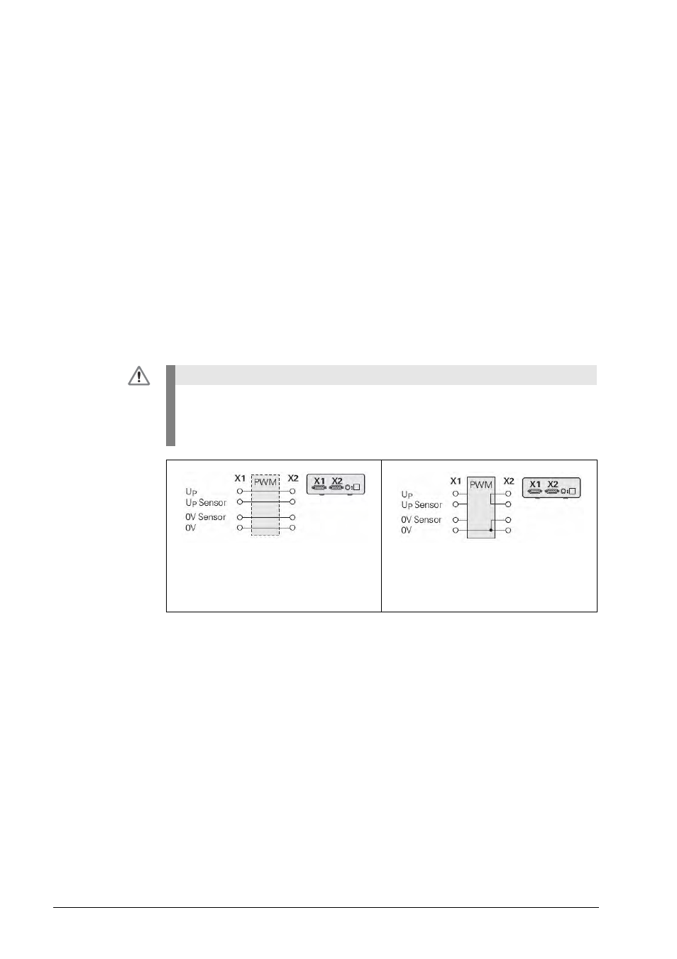
The supply and sensor lines are switched via the ATS software (as of ATS V2.6) depending
on the respective mode of operation and can be connected (see examples).
It is always ensured that the supply voltage generated by the PWM 20 is not present at X2.
Example 1:
PWM 20 in feed-through mode (encoder
powered by subsequent electronics) or
ATS software not started
Example 2:
PWM 20 powers the encoder via X1