Examples of encoders, Commutating signals, Incremental signals – HEIDENHAIN PWM 20 User Manual
Page 214: Reference mark signal, Connecting cables, 3 incremental signals1vpp with commutating signals
November 2014
Interface description
215
7.2.3 Incremental signals
1Vpp with commutating signals
Examples of
encoders
ERN 1085, ERN 1185, ERN 1387
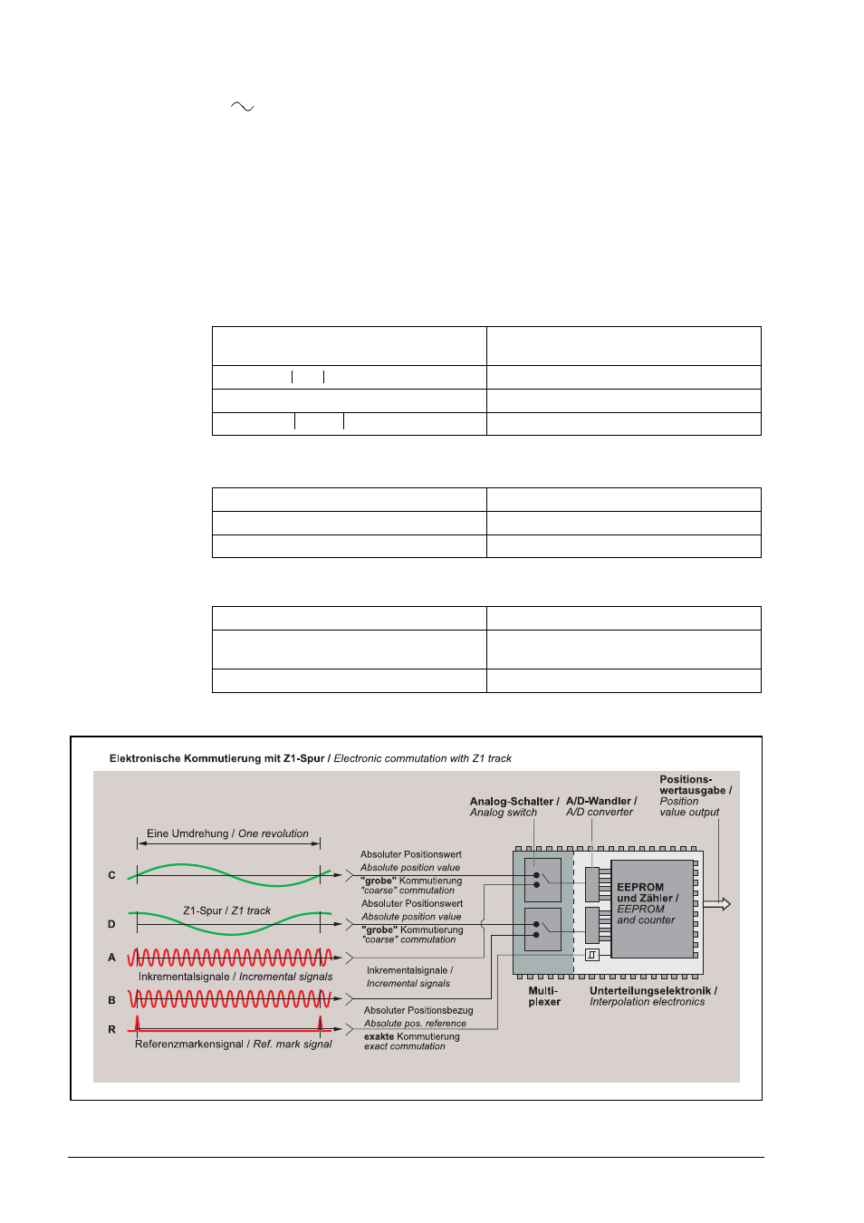
Commutating
signals
The commutating signals C and D are derived from the Z1 track, and are equal to one sine or
cosine period per revolution. Their typical signal amplitude is 1 Vpp (signal level: see incremental
signals A and B). The recommended input circuit of the subsequent electronics is the same as
for the 1 Vpp interface.
Incremental signals
Two nearly sinusoidal signals A and B
Reference mark
signal
One or several signal peaks R
Connecting cables
Signal amplitude M
0.75 to 1.2 Vpp
typ. 1 Vpp
Asymmetry /2M
0.05
TV
11.5°
Signal ratio M
A
/ M
B
0.9 to 1.1
Phase angle
/2
90°
5° el.
P - N
=ˆ
1 2
+
Usable component G
0.2 to 1.1 V
Signal-to-noise ratio E, F
min. 100 mV
Zero crossovers K, L
180°
90° el.
Shielded HEIDENHAIN cable
PUR [4(2 x 0.14 mm
2
) + (4 x 0.5 mm
2
)]
Cable length
Max. 150 m at 90 pF/m distributed
capacitance
Propagation time
6 ns/m