HEIDENHAIN PWM 20 User Manual
Page 240
November 2014
Interface description
241
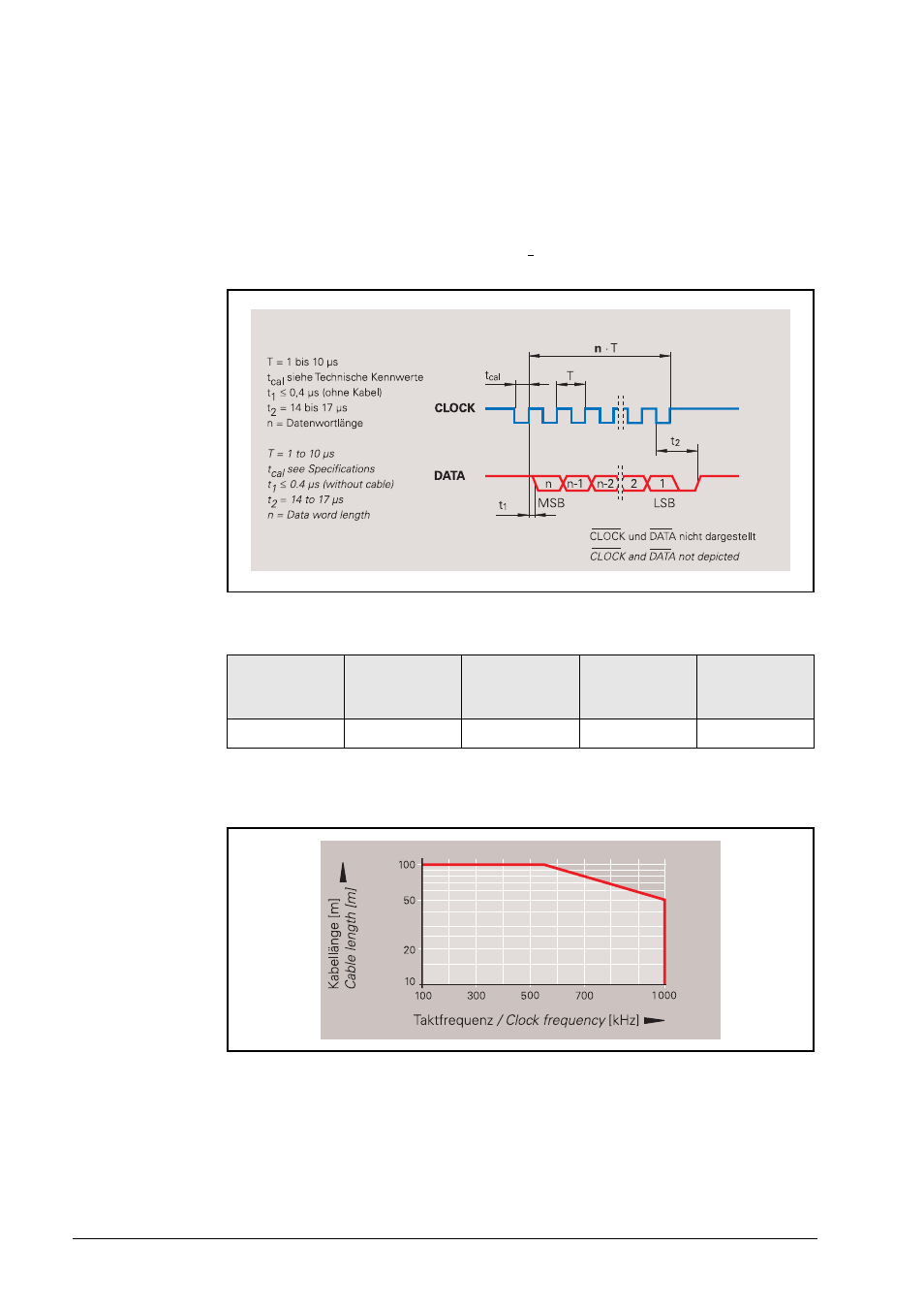
Control cycle for complete data word
In the quiescent state clock and data lines are on high level. The current position value is stored
on the first falling edge of the clock. Data transfer begins with the first rising clock edge.
When a complete data word was transferred the data output remains at low level, until the
encoder is ready for a new measured value latch (t2). If another data-output request (CLOCK)
is received within this time, the same data will be output once again.
If data output is interrupted (CLOCK = high for t t2) a new measured value is saved with the
next falling edge. With the next rising clock edge the subsequent electronics adopts the data.
Data word length n
Permissible clock frequency with respect to cable lengths
ROC 413
ECN 113
ECN 413
ROC 412
ROC 410
ROQ 424
ROQ 425
EQN 425
13 bits
13 bits
13 bits
25 bits
25 bits
>