3 square-wave interfaces, 1 incremental signals ttl square-wave interface, Examples of encoders – HEIDENHAIN PWM 20 User Manual
Page 215: Incremental signals, Reference mark signal, Fault-detection signal
216
HEIDENHAIN ATS Software User's Manual
7.3
Square-wave interfaces
7.3.1 Incremental signals
TTL square-wave interface
Encoders that output TTL square-wave signals feature electronics which digitize the sinusoidal
scanning signals without or with 2-fold interpolation. They provide two 90° (elec.) phase-shifted
square-wave pulses Ua1 and Ua2
and one or more reference pulses Ua0 which is gated with
the incremental signals. The fault-detection signal UaS indicates fault conditions such as
breakage of the power line or failure of the light source. It can be used for such purposes as
machine shut-off during automated production.
The integrated electronics also generate the inverted signals of all square-wave pulse trains.
The measuring step results from the spacing between two edges of the signals Ua1 and Ua2
subsequent to 1-fold, 2-fold or 4-fold evaluation.
The subsequent electronics must be designed to detect every edge of the square-wave pulses.
The minimum edge separation a stated in the specifications applies for the specified input
circuit with a cable length of 1 m and refers to a measurement at the output of the differential
line receiver. Cable-dependent differences in the propagation times additionally reduce the edge
separation by 0.2 ns per meter of cable. To prevent counting errors the subsequent electronics
must be designed such that it can operate with 90% of the resulting edge separation. The
maximum permissible shaft speed or traversing velocity must never be exceeded.
Examples of
encoders
ERN 120, ERN 420, ERN 1020, ROD 42x, ROD 1020
LS 176, LS 177, LS 328, LS 476, LS 477, LS 323, LS 623, LS 628, LIM 571
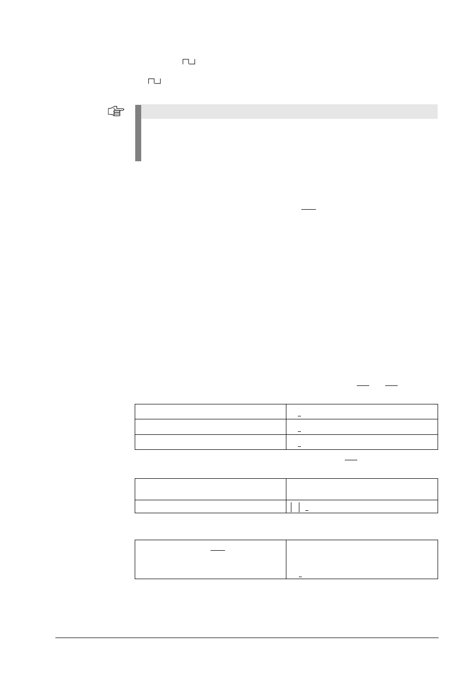
Incremental signals
Two TTL square-wave signals Ua1 and Ua2 and their inverted signals Ua1 and Ua2
Reference mark
signal
One or several square-wave pulses Ua0 and their inverted pulses Ua0
Fault-detection
signal
Note
The stated tolerances are standard values!
The tolerances of measuring systems for high resolutions (e.g. angle encoders) and large
temperature ranges (e.g. motor encoders) are tighter!
The supply voltage of 5 V
5% at the encoder has to be ensured!
Edge separation
a 0.45 µs at 300 kHz scanning frequency
a 0.8 µs at 160 kHz scanning frequency
a 1.3 µs at 100 kHz scanning frequency
>
>
>
Pulse width
90° elec. (other widths available on request);
LS 323: ungated (= 360° elec.)
Delay time
50 ns
t
d
<
(LS 176, LS 47x)
1 square-wave pulse UaS
Improper function: LOW
(upon request: Ua1/Ua2 at high impedance)
Proper function: HIGH
ts 20 ms
>