Yaskawa VS-616G5 Series Revision F Programming Manual User Manual
Page 12
V/f
V/f w/PG Open Loop
Vector
Flux
Vector
12
VS-616G5 Programming Manual
This function selects the stopping method suitable for the particular application.
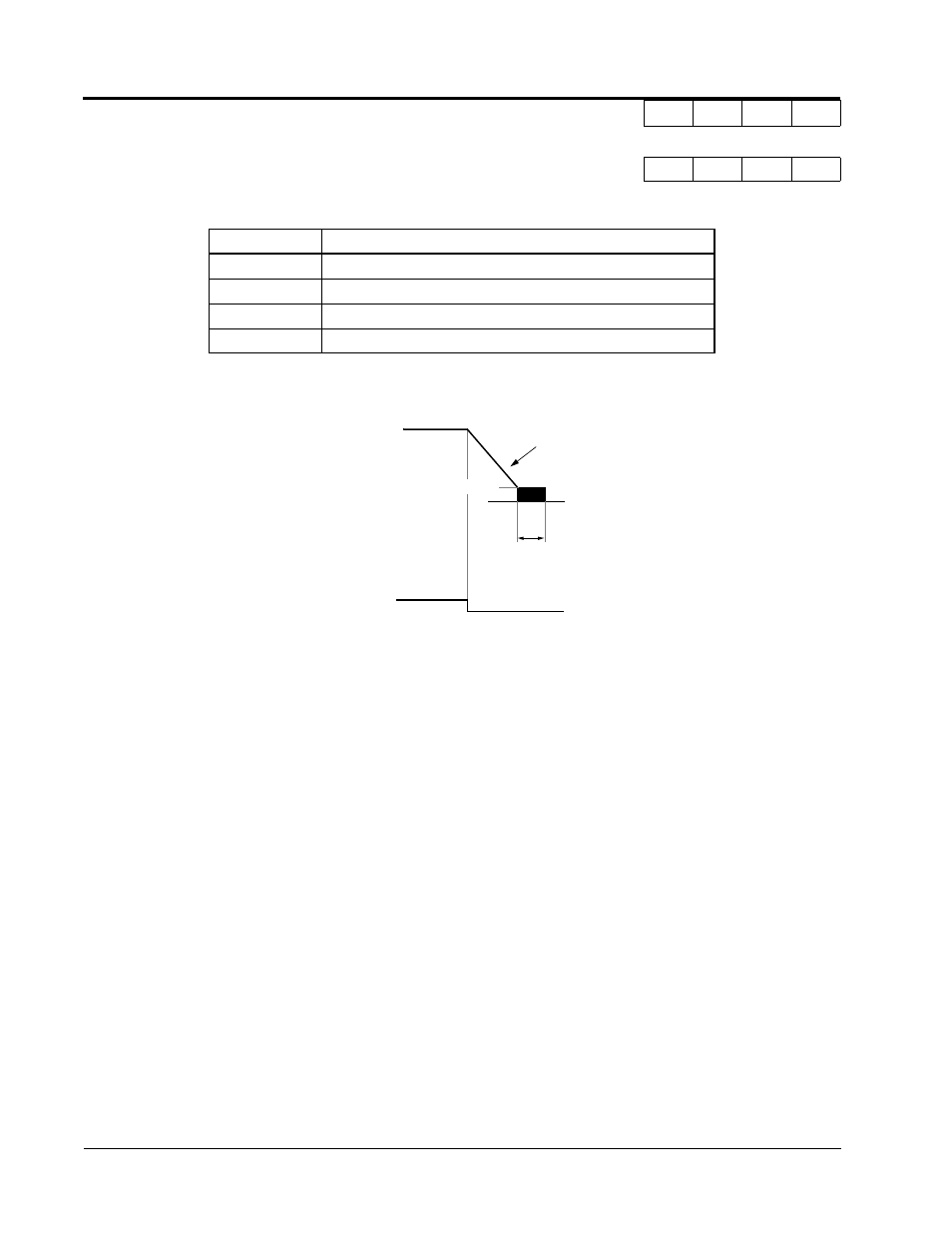
· Ramp to Stop (B1-03 = “0”)
Upon removal of the FWD (REV) run command, the motor decelerates at a rate determined by the
time set in deceleration time 1 (C1-02) and DC injection braking is applied after the minimum output
frequency (E1-09) has been reached. If the deceleration time is set too short or the load inertia is large,
an overvoltage fault (OV) may occur during deceleration. In this case, increase the deceleration time or
install an optional braking transistor and/or braking resistor (braking transistors are provided as stan-
dard for units 230V 7.5kW and smaller, 460V 15kW and smaller).
Braking torque: without braking resistor, approx. 20% of motor rated torque
with braking option, approx. 150% of motor rated torque
B1-03 Stopping Method Selection
Stopping Method
Q
Q
Q
Q
Setting
Description
0
Ramp to stop (factory default)
1
Coast to stop
2
DC injection to stop
3
Coast to stop with timer
Output Frequency
Decel time 1 (C1-02)
Run Command
ON
OFF
DC injection Braking Time
at Stop (B2-04)
Factory Default: 0.5 s
DC Injection Braking Start - B2-01)
Factory Default: 0.5Hz
Zero Speed Level (Frequency at
Figure 1 Stopping Method - Ramp to Stop
Section B: Application Parameters
B1 Sequence