Yaskawa VS-616G5 Series Revision F Programming Manual User Manual
Page 88
V/f
V/f w/PG Open Loop
Vector
Flux
Vector
88
VS-616G5 Programming Manual
Section H: Control Circuit Terminals
H2 Digital Outputs
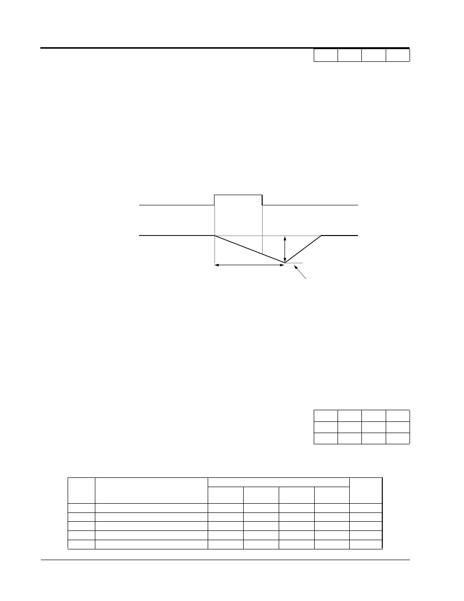
· KEB Ridethrough (settings: N.C. = “65”, N.O. = “66”)
In general applications, the Kinetic Energy Braking (KEB) control circuit attempts to maintain the
DC bus voltage at an optimum level [1.35 × input voltage (E1-01)] during momentary power loss, by
using load inertia to regenerate voltage back to the DC bus. The inverter decelerates at the fast-stop
rate (C1-09), until power is restored, or until the time runs out and an undervoltage fault (UV)
occurs. The larger the inertia, the longer the deceleration rate can be extended. If the inertia is small,
then the inverter must decelerate quickly to regenerate voltage back to the DC bus, and thus the ride-
through time is shorter. For most applications, set KEB Frequency Constant (L2-06) to “0” (factory
default).
.
Note:
Larger model inverters (2022 and above, 4018 and above) require a separate uninterruptible
power supply (UPS) for control power, in order for load inertia ridethrough to be effective.
H2
Digital Outputs
The VS-616G5 has three multi-function contact outputs for the indication of various conditions,
including frequency detection, speed agree, zero speed, overtorque detection, and many others. This
section includes descriptions of these functions.
The following table lists the function selections for the multi-function contact outputs (terminals 9, 25
and 26), and indicates the control modes during which each function can be enabled.
H2-01 Multi-function Output 1 Selection (terminal 9, 10) Terminal 9 Sel
B
B
B
B
H2-02 Multi-function Output 2 Selection (terminal 25, 27) Terminal 25 Sel
B
B
B
B
H2-03 Multi-function Output 3 Selection (terminal 26, 27) Terminal 26 Sel
B
B
B
B
H2-01
to 3
Setting
Function
Control Method (A1-02)
Reference
Page
V/f
V/f w/ PG
Open Loop
Vector
Flux Vector
0
During run 1 (factory default, H2-01)
√
√
√
√
1
Zero-speed (factory default, H2-02)
√
√
√
√
2
Frequency agree 1 (factory default, H2-03)
√
√
√
√
3
Desired frequency agree 1
√
√
√
√
4
Frequency detection 1
√
√
√
√
KEB Ridethrough
ON
OFF
Output Frequency
L2-06
C1-09
OFF
C1-01
Figure 36 KEB Ridethrough Timing Diagram
Multi-function Input Contact
(H1-__ = “65” or “66”)
1.35 × E1-01