Hcontrol circuit terminal parameters – Yaskawa VS-616G5 Series Revision F Programming Manual User Manual
Page 76
V/f
V/f w/PG Open Loop
Vector
Flux
Vector
76
VS-616G5 Programming Manual
Section H: Control Circuit Terminals
H1 Digital Inputs
The setting of parameter F9-06 selects the stopping method when an BUS fault is detected.
A BUS fault may occur when using the SI-B or the CP-916 communication options. The fault will
occur after initial communication has been established then the connection is lost. The following fault
code will be displayed: “BUS SI-B Com Err”.
H
Control Circuit Terminal Parameters
H1
Digital Inputs
The VS-616G5 has six multi-function contact inputs for the set-up of numerous functions, including
multi-step speed operation, PID, speed search, speed/torque control selection, and many other. This
section includes descriptions of these functions.
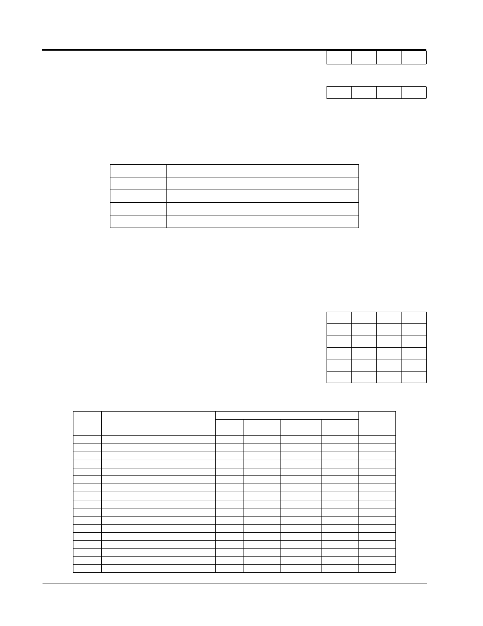
The following table lists the function selections for the multi-function contact inputs (terminals 4 to 8),
and indicates the control modes during which each function can be enabled.
F9-06
Bus Fault Select
Bus Fault Sel
A
A
A
A
Setting
Description
0
Ramp to Stop - Ramp to stop according to C1-02 set value.
1
Coast to stop.
2
Fast-Stop - Ramp to stop according to C1-09 set value.
3
Alarm Only - Alarm flashes, operation continues.
H1-01 Multi-function Input Terminal 3 Selection
Terminal 3 Sel
B
B
B
B
H1-02 Multi-function Input Terminal 4 Selection
Terminal 4 Sel
B
B
B
B
H1-03 Multi-function Input Terminal 5 Selection
Terminal 5 Sel
B
B
B
B
H1-04 Multi-function Input Terminal 6 Selection
Terminal 6 Sel
B
B
B
B
H1-05 Multi-function Input Terminal 7 Selection
Terminal 7 Sel
B
B
B
B
H1-06 Multi-function Input Terminal 8 Selection
Terminal 8 Sel
B
B
B
B
H1-01
to 6
Setting
Function
Control Method (A1-02)
Reference
Page
V/f
V/f w/ PG
Open Loop
Vector
Flux Vector
0
3-Wire Control
√
√
√
√
1
Local/Remote Selection
√
√
√
√
2
Option/Inverter Selection
√
√
√
√
3
Multi-Step Ref. 1 (factory default, H1-03)
√
√
√
√
4
Multi-Step Ref. 2 (factory default, H1-04)
√
√
√
√
5
Multi-Step Reference 3
√
√
√
√
6
Jog Frequency Ref. (factory default, H1-05)
√
√
√
√
7
Multi-Accel/Decel 1
√
√
√
√
8
Ext. Baseblock N.O. (factory default, H1-06)
√
√
√
√
9
External Baseblock N.C.
√
√
√
√
A
Accel/Decel Ramp Hold
√
√
√
√
B
OH2 Alarm Signal
√
√
√
√
C
Terminal 16 Enable
√
√
√
√
D
V/f Mode Selection
−
√
−
−
E
ASR Integral Reset
−
√
−
√
10
MOP Increase
√
√
√
√
11
MOP Decrease
√
√
√
√