Yaskawa VS-616G5 Series Revision F Programming Manual User Manual
Page 99
VS-616G5 Programming Manual
99
H4
Analog Outputs
The VS-616G5 has two analog outputs, for the external monitoring of drive conditions such as output
frequency, output current, PID feedback and others.
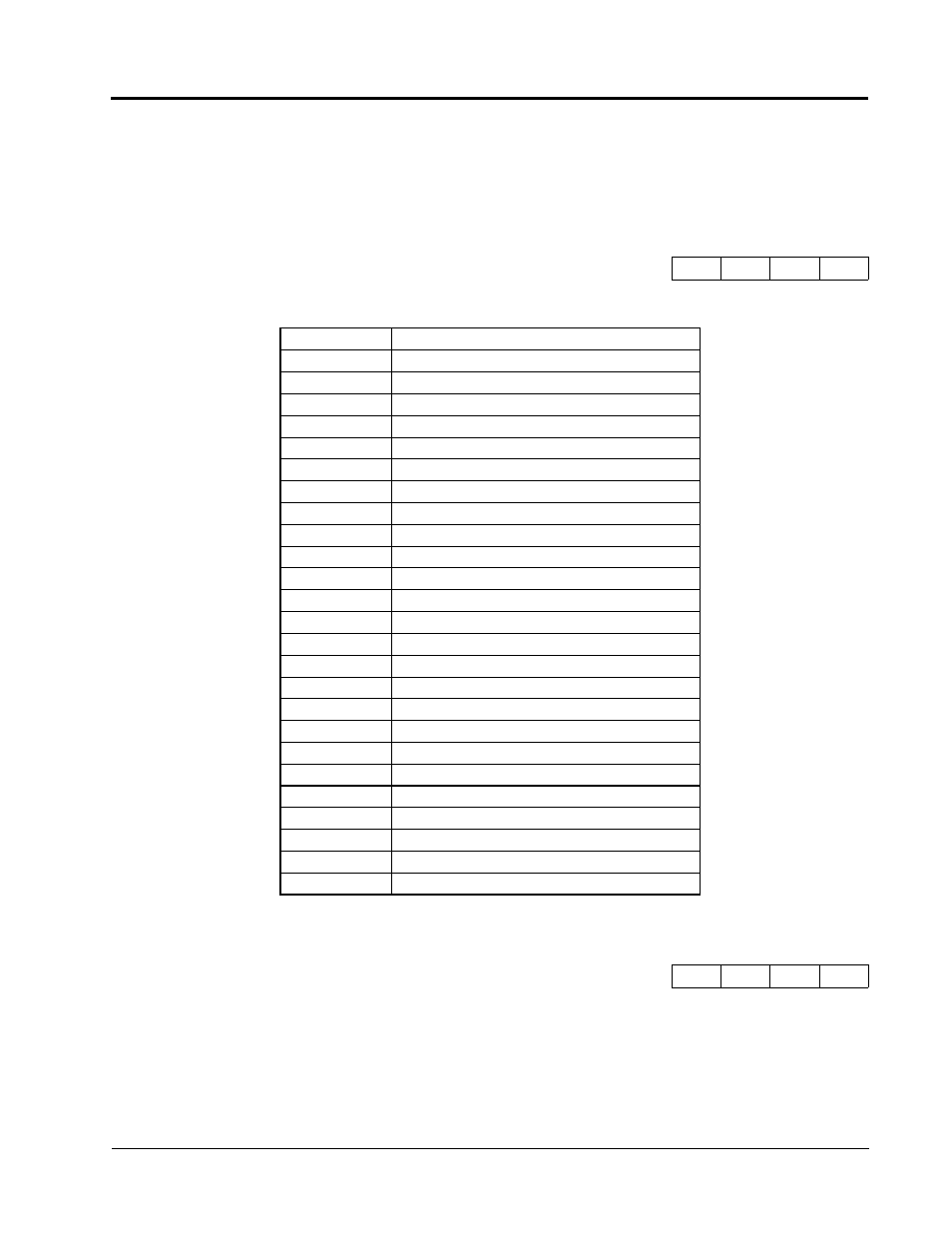
Selects the analog output monitors for terminal 21.
The resolution of terminal 21 is 9 bit plus sign.
Setting Range:
0.00 to 2.50
Factory Default:
1.00
Sets the terminal 21 output gain for the analog output monitors. To obtain the output level, multiply the
monitor output level by the gain value set in H4-02.
H4-01 Terminal 21 Analog Output Selection
Terminal 21 Sel
B
B
B
B
Setting
Description
1
Frequency reference
2
Output frequency (factory default)
3
Inverter output current
5
Motor speed
6
Output voltage
7
DC bus voltage
8
Output power
9
Torque reference (internal)
15
Terminal 13 input voltage level
16
Terminal 14 input voltage or current level
17
Terminal 16 input voltage level
18
Motor secondary current (Iq)
19
Motor excitation current (Id)
20
SFS output frequency
21
ASR input
22
ASR output
23
Speed deviation
24
PID feedback
26
Voltage reference (Vq output)
27
Voltage reference (Vd output)
32
ACR (q) Output
33
ACR (d) Output
36
PID Input Monitor
<1110>
37
PID Output Monitor
<1110>
38
PID Setpoint Monitor
<1110>
H4-02 Terminal 21 Analog Output Gain
Terminal 21 Gain
B
B
B
B
Section H: Control Circuit Terminals
H4 Analog Outputs