Analog output channel 1 selection (continued) – Yaskawa VS-616G5 Series Revision F Programming Manual User Manual
Page 69
VS-616G5 Programming Manual
69
V/f
V/f w/PG Open Loop
Vector
Flux
Vector
Setting Range:
0.00 to 2.50
Factory Default:
1.00
Sets the channel 1 output gain for the analog output monitors. To obtain the output level, multiply the
monitor output level by the gain value set in F4-02.
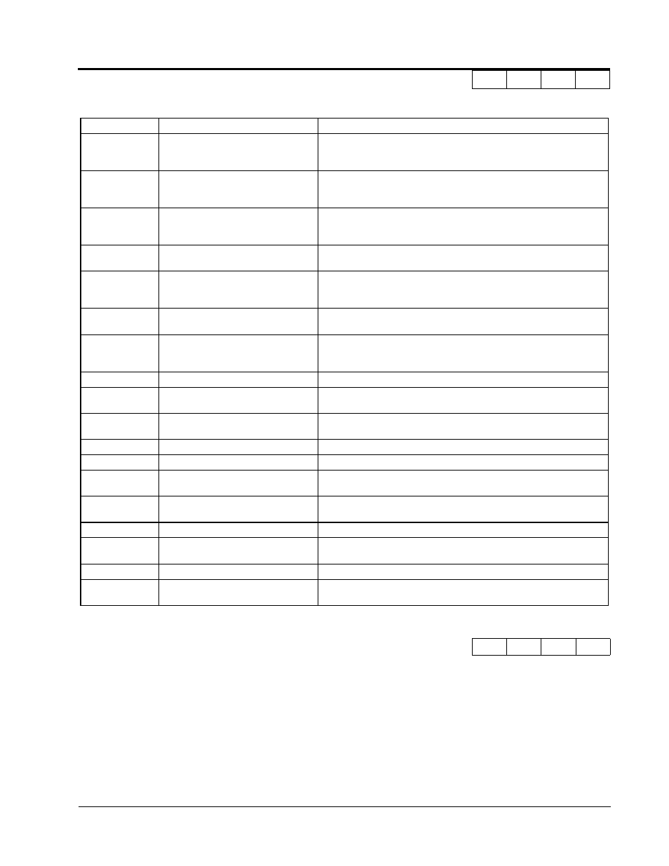
18
Motor secondary current (Iq)
Monitors the calculated value of the motors secondary current. (Iq) The motors
rated secondary current corresponds to 100%. 10 V=Rated secondary current.
(0 to + 10 V output)
19
Motor excitation current (Id)
Monitors the calculated value of the motors excitation current. (Id) The motors
rated excitation current corresponds to 100%. 10 V=Rated excitation current. (0
to + 10 V output).
20
SFS output frequency
Monitors the output frequency after a soft start. This is the frequency without the
correction from compensation functions such as slip compensation. 10 V=Max.
frequency (0 to +/- 10 V possible)
21
ASR input
Monitors the input to the speed control loop. The max. frequency corresponds to
100%. 10 V=Max. frequency (0 to +/- 10 V possible)
22
ASR output
Monitors the output from the speed control loop. Analog monitor becomes 10 V/
max. output frequency with V/F control. In vector control the analog monitor be-
comes 10V= motor rated excitation current. (0 to +/-10V possible.)
23
Speed deviation
Monitors the speed deviation within the speed control loop. The max. frequency
corresponds to 100%. 10 V=Max. frequency (0 to +/-10 V possible.)
24
PID feedback
Monitors the feedback value when the PID control is utilized. The input for the
max. frequency corresponds to 100%. 10 V= Max frequency.
(0 to +/-10 V possible.)
25
Not Used
--
26
Voltage reference (Vq output)
Monitors the inverters internal voltage reference value for the motors secondary
current control. 10 V= 200,400 or 575 VAC (0 to =/- 10 V possible.)
27
Voltage reference (Vd output)
Monitors the inverters internal voltage reference value for the motors excitation
current control. 10 V= 200,400 or 575 VAC (0 to =/- 10 V possible.)
28-30
Not Used
--
31
Not Used
--
32
ACR(q) Output
Monitors current control output value for the motors secondary current.
10 V= 100%.
33
ACR(d) Output
Monitors current control output value for the motors excitation current.
10 V= 100%.
34-35
Not Used
--
36
PID Input Monitor
Monitors the input to the PID circuit. This is the PID reference + the PID reference
bias - the PID feedback. 10 V= Max frequency.
37
PID Output Monitor
Monitors the output of the PID circuit. 10 V= Max frequency.
38
PID Setpoint or Reference
Monitors the PID setpoint. This is the PID setpoint + the PID setpoint bias.
10 V= Max frequency.
F4-02 Analog Output Channel 1 Gain
AO CH1 Gain
A
A
A
A
Analog Output Channel 1 Selection (Continued)
F4-01 Setting
Function
Description
Section F: Option Parameters
F4 AO-08/AO-12 Option Set-up