Yaskawa VS-616G5 Series Revision F Programming Manual User Manual
Page 81
VS-616G5 Programming Manual
81
V/f
V/f w/PG Open Loop
Vector
Flux
Vector
· Speed Control Integral Value Reset (setting: “E”)
The speed control integral value can be reset while the inverter is running when this function is
selected. Reset is effective only when integral control selection during accel/decel (F1-07) = “0”.
Open:
PI-control (speed control integral values are added.)
Closed:
P-control (speed control integral values are reset by the integral time constant.)
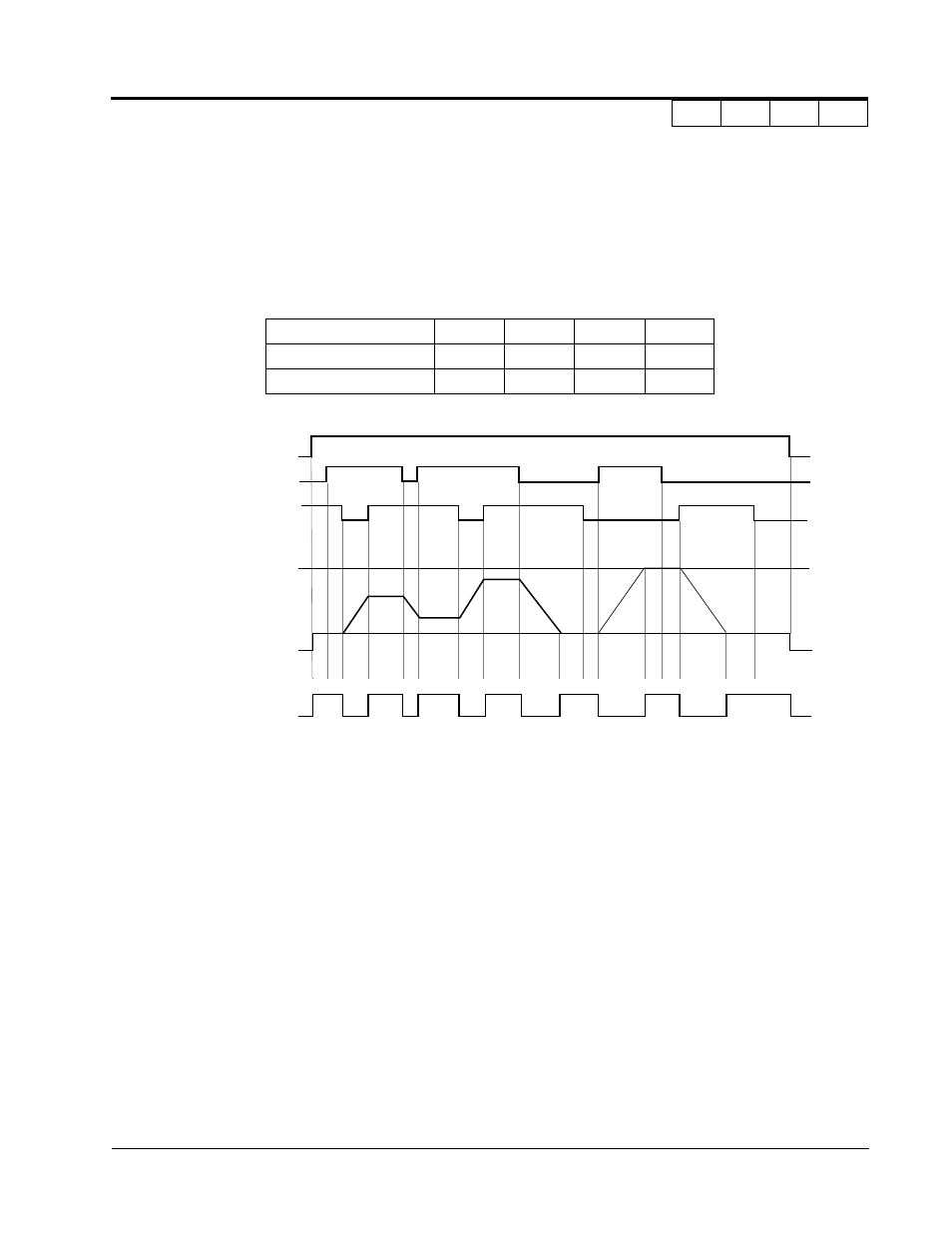
· Up/Down Command (settings: Up = “10”. Down = “11”)
With the FWD (REV) run command entered, a change in frequency is performed by inputting the Up
or Down signals to any two contact inputs, so that operation can be performed at the desired speed.
Notes:
1.
Be sure to set frequency reference selection (B1-01) = “1”. When B1-01 = “0”, Up/Down
operation is disabled.
2.
Upper limit speed
= Max. output frequency (E1-04) × Frequency reference upper limit (D2-01), if used
3.
The lower limit value is either the master frequency reference from control circuit terminals
13 or 14, or the frequency reference lower limit (D2-01), whichever is larger.
4.
When hold reference memory selection is enabled (D4-01 = “1”) and a hold command is
input, the held output frequency is stored even after the power supply is turned OFF.
When D4-01 = “0”, the held output frequency is not stored.
5.
If the jog frequency reference is input during Up/Down operation, the jog frequency ref-
erence has priority.
UP command
Closed
Open
Open
Closed
DOWN command
Open
Closed
Open
Closed
Operation Status
Accel
Decel
Hold
Hold
Figure 33 UP/DOWN Command Timing Diagram
FWD Run
UP Command S5
DOWN Command S6
Upper Limit Speed
Lower Limit Speed
Output Frequency
Frequency Agree Signal
D H U
U1
D1
D1
D
D
D
H
H
H
H
H
U
U
H
U:
Up (accelerating) status
D:
Down (decelerating) status
H:
Hold (constant speed) status
U1: Up status, with clamping at upper limit speed
D1: Down status, with clamping at lower limit speed
Section H: Control Circuit Terminals
H1 Digital Inputs