Yaskawa VS-616G5 Series Revision F Programming Manual User Manual
Page 50
V/f
V/f w/PG Open Loop
Vector
Flux
Vector
50
VS-616G5 Programming Manual
Setting Range:
0 to 120%
Factory Default:
10%
Sets the speed limit bias value in the torque control mode as a percentage of the maximum output fre-
quency.
Setting Range:
0 to 1000ms
Factory Default:
0ms
Sets delay time from when the speed/torque control selection is made to when the control mode is
actually changed, in units of 1ms.
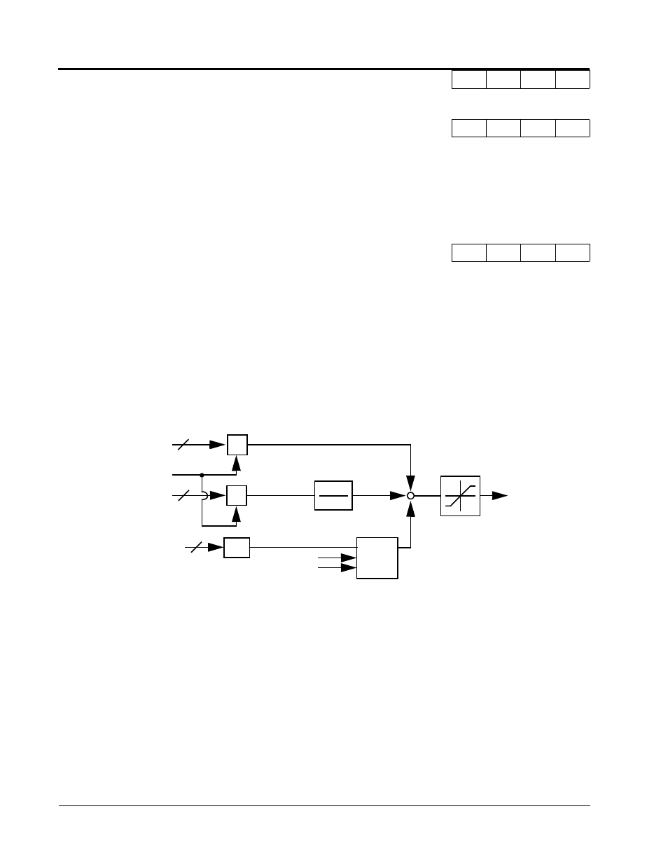
Torque Control Operation
To select torque control, set torque selection (D5-01) to “1”, or close the multi-function contact input
set to speed/torque control (H1-__ = “71”) and set terminal 16 function selection to torque reference
(H3-05 = “13”).
*1: When speed limit selection (D5-03) is set to “1”, the master frequency reference input from termi-
nal 13 or 14 becomes the speed limit; when speed limit selection (D5-03) is set to “2”, the set value
of D5-04 becomes the speed limit.
*2: When terminal 14 function selection is set to torque compensation (H3-09 = “14”), terminal l4 set
value can be used as the torque compensation value.
When torque reference > 0 and speed limit > 0 (winder application sequence), the following sequence
is activated:
D5-05 Speed Limit Bias
Speed Lmt Bias
-
-
-
A
D5-06 Reference Delay Timer
Ref Hold Time
-
-
-
A
Speed
1
1 + ST
Torque Limit
Iq
+
+
Figure 27 Torque Control Block Diagram
Limiting
Circuit
SFS
T = D5-02
÷
÷
+
Motor Speed
D5-05
Torque
Compensation
*2
Torque
Reference
Speed Limit
*1
Section D: Reference Parameters
D5 Torque Control