Yaskawa VS-616G5 Series Revision F Programming Manual User Manual
Page 48
V/f
V/f w/PG Open Loop
Vector
Flux
Vector
48
VS-616G5 Programming Manual
D4
Sequence
Selects whether the held frequency during motor operated potentiometer (MOP) simulation operation
is stored when operation is stopped (when power is removed or when the run command is removed).
Note: MOP operation is set using the multi-function contact input function selections (H1-01 to H1-06,
setting = “10” and “11”). See section H1, Digital Inputs, on page 76 for more information.
Setting Range:
0 to 100%
Factory Default:
10%
Sets the motor operated pot or “trim” control level as a percentage of maximum output frequency in
units of 1%. When trim control increase and decrease are selected as multi-function contact input func-
tions (setting: H1-__ = “1C” and “1D”, respectively), the trim control level is added to or subtracted
from the analog frequency reference, when each respective contact closes. This is useful in applica-
tions such as winders and unwinders, where speed compensation may be needed.
D4-01 Hold Reference Memory Selection
MOP Ref Memory
A
A
A
A
Setting
Description
0
Held frequency during MOP operation not retained. If a stop command is given or if
power is removed, the frequency reference is reset to 0Hz. If the inverter is still decel-
erating when the run command is restored, operation resumes at the frequency refer-
ence which the inverter has ramped down to (factory default).
1
Held frequency during MOP operation is retained. If a stop command is given, or if
power is removed, operation resumes at the held frequency reference when run com-
mand is restored.
D4-02 Trim Control Level
Trim Control Lvl
A
A
A
A
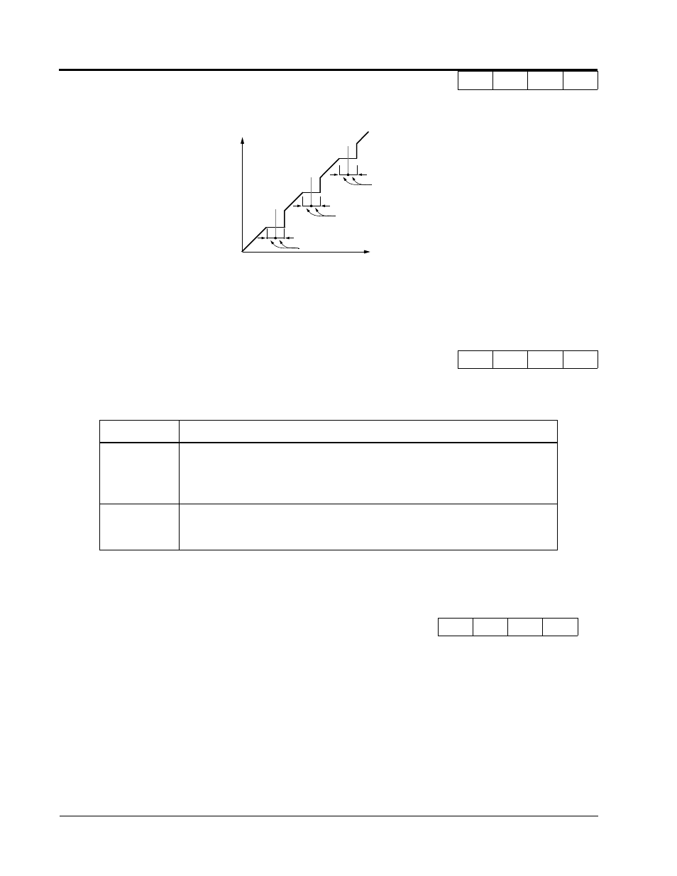
Hz
D3-02
D3-01
D3-04
D3-04
Hz
Set Frequency Reference
Figure 26 Jump Frequencies
D3-03
D3-04
Output
Frequency
Section D: Reference Parameters
D4 Sequence