Yaskawa VS-616G5 Series Revision F Programming Manual User Manual
Page 72
V/f
V/f w/PG Open Loop
Vector
Flux
Vector
72
VS-616G5 Programming Manual
Section F: Option Parameters
F6 DO-08 Option Set-up
F6
DO-08 Set-up
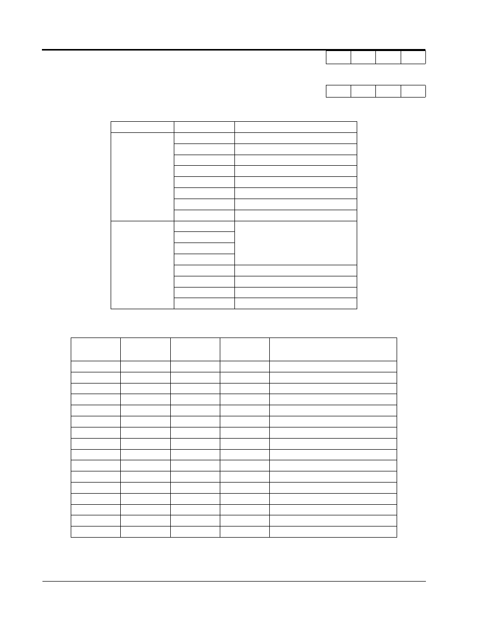
Selects the multi-function output selections for the DO-08 option.
* When F6-01 is set to binary output (setting = “1”), use the table below to read the DO-08 output.
Note: When the terminal is open, the bit setting is “0”; when the terminal is closed, the bit setting is “1”.
F6-01 DO-08 Digital Output Selection
DO-08 Selection
A
A
A
A
Setting
Terminal No.
Description
0
8-channel
individual
(factory default)
TD5/TD11
Overcurrent (SC, OC, GF)
TD6/TD11
Overvoltage (OV)
TD7/TD11
Inverter overload (OL2)
TD8/TD11
Fuse blown (FU)
TD9/TD11
Not used
TD10/TD11
Inverter overheat (OH)
TD1/TD2
During zero-speed detection
TD3/TD4
During speed agree
1
binary output
TD5/TD11
Binary output *
TD6/TD11
TD7/TD11
TD8/TD11
TD9/TD11
During zero-speed detection
TD10/TD11
During speed agree
TD1/TD2
During run
TD3/TD4
Minor fault
TD8/TD11
(bit 3)
TD7/TD11
(bit 2)
TD6/TD11
(bit 1)
TD5/TD11
(bit 0)
Description
0
0
0
0
No fault
0
0
0
1
Overcurrent (SC, OC, GF)
0
0
1
0
Overvoltage (OV)
0
0
1
1
Inverter overload (OL2)
0
1
0
0
Inverter overheat (OH)
0
1
0
1
Overspeed (OS)
0
1
1
0
Fuse blown (FU)
0
1
1
1
Not used
1
0
0
0
External fault (EF3 ~ EF8)
1
0
0
1
Controller fault
1
0
1
0
Motor overload (OL1)
1
0
1
1
Not used
1
1
0
0
Power loss (UV1, UV2, UV3)
1
1
0
1
Excessive speed deviation (DEV)
1
1
1
0
PG disconnection (PGO)
1
1
1
1
Not used