Preparation/removal – Paxton Superchargers Ford Mustang GT User Manual
Page 37
P/N: 4809654 v5.0
©2010 Paxton Automotive
All Rights Reserved, Intl. Copr. Secured
17
F. Slide the two 2.691" long spacers onto the bolts
previously installed. (See Fig. 6-f.) Install the
small triangle-shaped idler pulley mounting
bracket to the spacers. Install the .097" spacer
onto the bolt that will be attached in the alterna-
tor location.
G. Lower the mounting plate assembly into posi-
tion on the front of the engine. Be sure to route
the drive belt on the correct side of the idler
bracket and spacers. (See Fig. 6-g.)
H. Loosely attach the plate using the previously
installed 140mm hardware. Locate the two 3/8-
16 x 1.0" bolts and washers and install through
the plate into the two stud bolt spacers retaining
the factory idlers. (See Figs. 6-a, 6-b.)
6. SUPERCHARGER MoUNTiNG PLATE
iNSTALLATioN
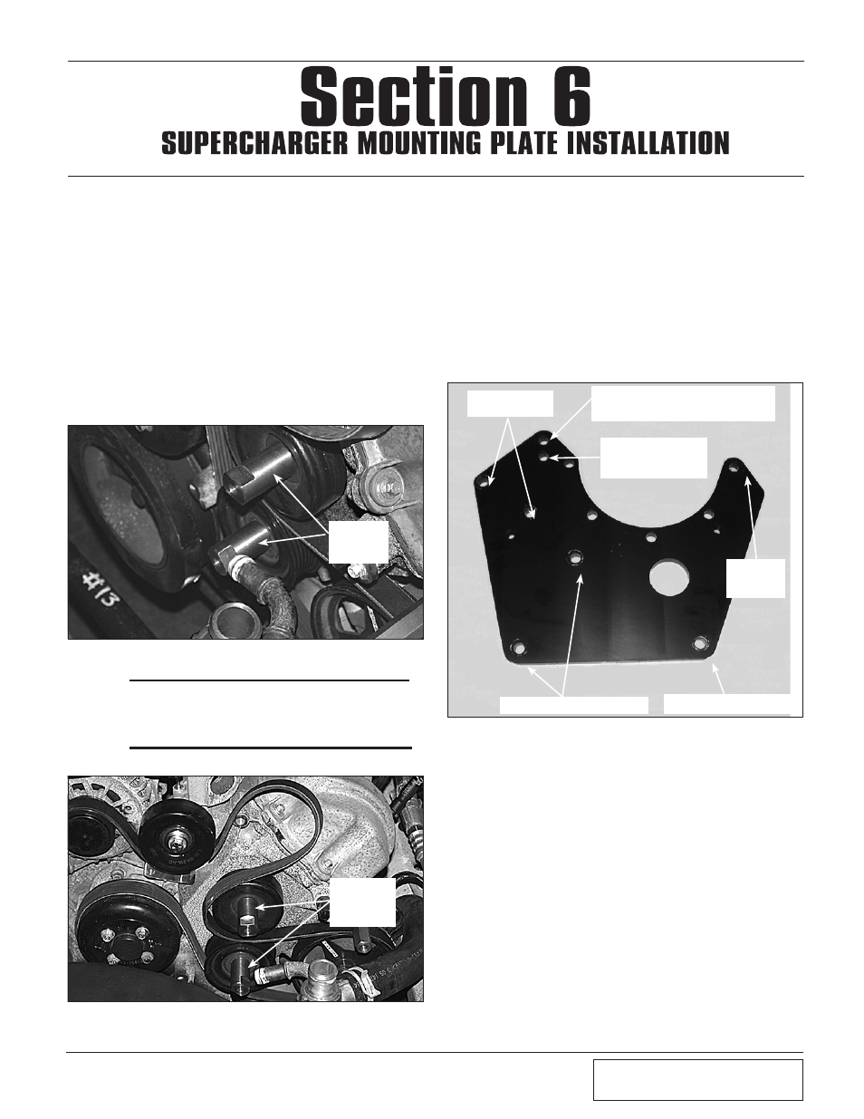
Fig. 6-c
Fig. 6-a
Fig. 7-b
2 x 8mm x
140mm SCREWS
8mm x 150mm SCREW
2 x 3/8-16 x 1.0" SCREWS
2005-2008 H.O.
IDLER LOCATION
(3/8 16 x 3.75" SCREW)
5 x 3/8-16
x 1.0"
SCREWS
STUD
BOLT
SPACERS
STUD
BOLT
SPACERS
INSTALLED
2005-2008 NON-COOLED AND 2010
H.O. MODEL IDLER LOCATION,
(3/8 16 x 3.75" SCREW)
A. The mounting plate is provided with the spacers
and bolts as they would be installed on the
vehicle. Keep these bolts and spacers marked as
to their locations. They are all different in size
and mismatching them will result is misalign-
ment of the mounting plate.
B. Locate the two supplied stud bolt spacers (see
Figs. 6-a, 6-b) in the S/C mounting plate
assembly. Remove the factory screws retaining
the idler pulleys on the driver’s side of the
engine and replace with the stud spacers.
C. It is necessary to install the supercharger acces-
sory drive belt and loosely route it following
Fig. 6-e, as not all pulleys are currently in
place.
D. Locate the supercharger mounging plate
4FU010-044 from the supercharger mounting
plate assembly. (See Fig. 6-c.)
E. Locate the two 8mm x 140mm long bolts and
washers from the mounting bracket assembly
and install in the locations noted. (See Fig.
6-c.)
*** NOTE ***
This figure is just for reference. The small idler pulley
mounting bracket will need to be installed at the same
time as the S/C Mounting Plate. (See Fig. 6-d.)
Section 1
PREPARATION/REMOVAL