Paxton Superchargers Ford Mustang GT User Manual
Page 68
P/N: 4809654 v5.0
©2010 Paxton Automotive
All Rights Reserved, Intl. Copr. Secured
48
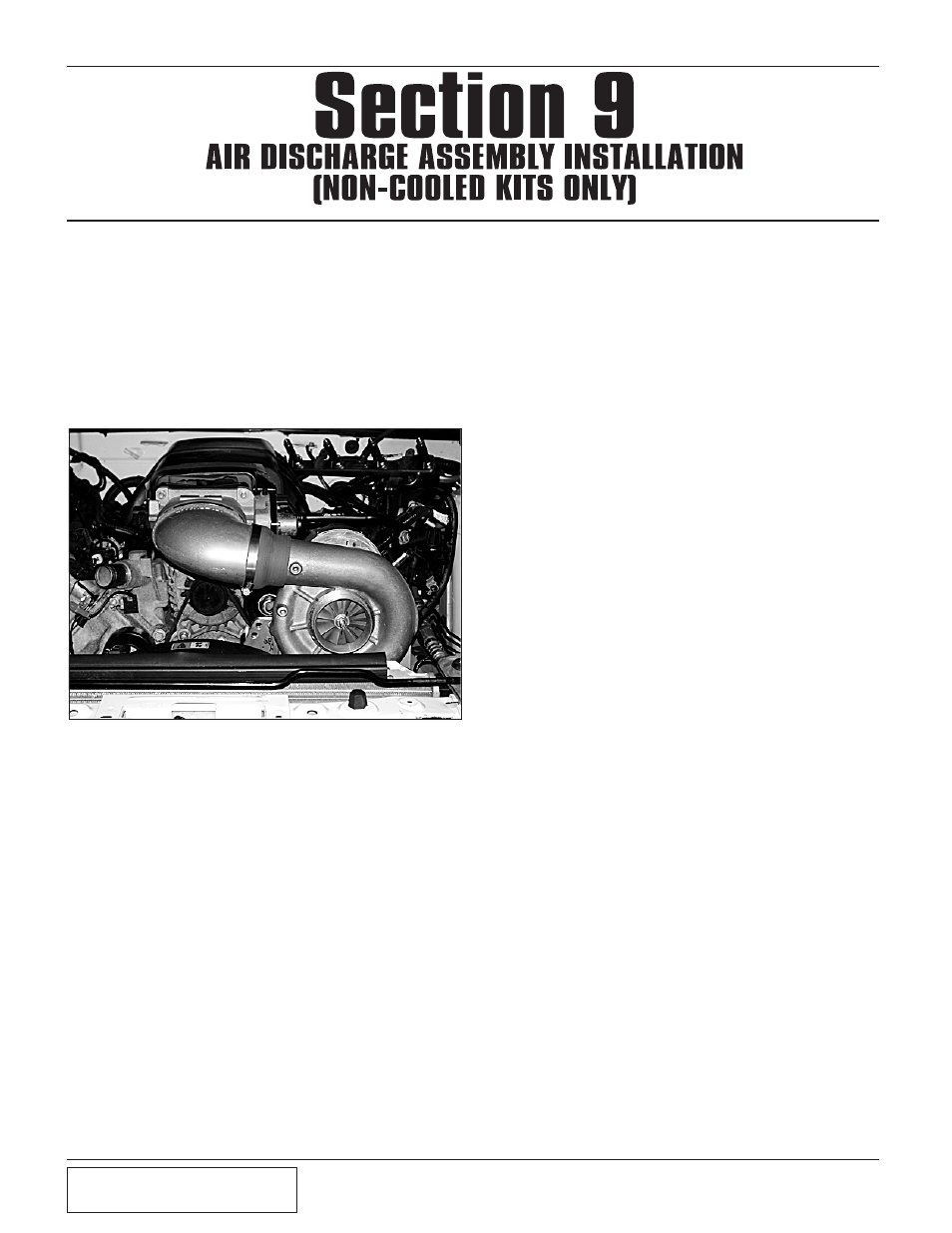
A. Attach the 4.5" sleeve to the discharge duct
with the #72 clamps provided.
B. Install the 3.0" x 2.75" reducer to the inlet of
the discharge duct.
C. Install the duct to the inlet of the throttle body
and the outlet of the supercharger. (See Fig.
9-a.)
H. Connect the supplied length of 5/32" vacuum to
the port on the bypass valve. Route the line to
the fuel regulator vacuum hose. Using the sup-
plied vacuum TEE, connect the bypass vacuum
line. (See Figs. 9-b, 9-c on Page 9-2, for assis-
tance.)
9. AiR DiSCHARGE ASSEMBLy
(Non-Cooled
kits only)
Fig. 9-a
D. Assemble the compressor by-pass valve by
using a piece of 1" hose cut 15" long and a
piece cut to 4.25" long, and four #16 hose
clamps.
E. Attach the 4.25" piece of hose to the inlet of the
by-pass and secure with a #16 clamp. (See Fig.
9-b.)
F. Secure the 15" piece to the by-pass valve outlet
using a #16 hose clamp. (See Fig. 9-b.)
G. Attach the open end of the 4.25" hose to the 1"
boss on the air discharge duct. Secure with a
#16 hose clamp. The open end of the 15" long
hose will be connected to the air inlet in a
future step.
Section 9
AIR DISCHARGE ASSEMBLY INSTALLATION
(NON-COOLED KITS ONLY)