Paxton Superchargers Ford Mustang GT User Manual
Page 39
P/N: 4809654 v5.0
©2010 Paxton Automotive
All Rights Reserved, Intl. Copr. Secured
19
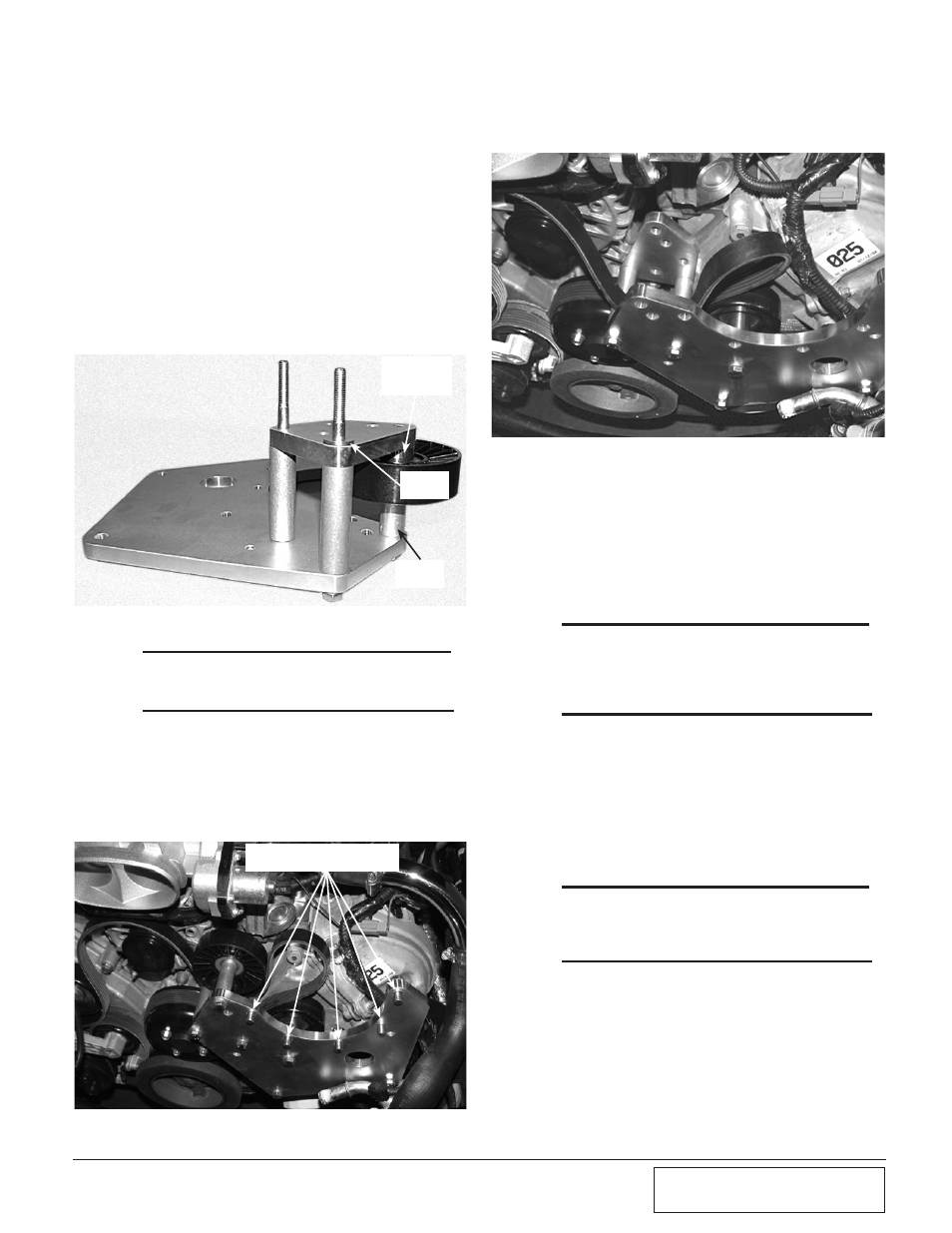
Fig. 6-f
Fig. 6-h
Fig. 6-g
*** NOTE ***
All kits will use the upper idler hole except for 2005-
2008 H.O. kits. (See Fig. 6-c.)
K. Tighten all mounting plate hardware, making
sure the drive belt is properly routed and no
wiring or hoses are between the mounting sur-
faces. (See Fig. 6-g.)
SUPERCHARGER
HARDWARE
.097"
SPACER
1.776"
SPACER
IDLER
PILOT
SPACER
I. Locate the 8mm x 150mm bolt and washer.
Loosely install the bolt through the mounting
plate and remaining 2.712" long spacer into the
engine cover using Fig. 6-a for location refer-
ence.
J. Locate the supplied idler, 1.776" idler spacer,
idler pilot spacer, 3/8-16 x 3.75" long bolt and
washer. Install the bolt/washer through the
mounting plate, 1.776" spacer, supplied idler,
idler pilot spacer and into the triangle-shaped
bracket. Use Figs. 6-f to 6-h for assistance.
M.* Attach the supplied length of 1/2" oil drain line
hose to the 1/2" barbed fitting on the super-
charger. Secure with the #8 hose clamp provid-
ed.
N.* Install the supplied 1/8"NPT x -4 straight fitting
from assembly 4FU130-026 to the oil feed fit-
ting on the supercharger.
*** NOTE ***
Use only clean engine oil on the pipe threads. Teflon
tape or pipe sealant is not recommended as if might
loosen and cause blockage of the small oil feed orifice
resulting in possible supercharger failure.
O. Attach the supercharger assembly to the mount-
ing plate using the previously installed hard-
ware. A 9/16" ratcheting end wrench will great-
ly aid this step.
P.* Secure the oil drain hose to the prevously
installed brass fitting in the oil pan, making
sure to route in a smooth downward manner
away from moving or hot objects.
*** NOTE ***
Any dips, “uphill” sections, kinks or restrictions may
cause drainage problems and possible supercharger
failure.
Q.* Attach the -4 oil feed hose to the straight -4 fit-
ting previously installed in the supercharger.
Secure away from moving of hot objects.
R. Using a 1/2" ratchet, rotate the factory spring
tensioner clockwise and install the accessory
drive belt. Refer to Fig. 6-e for proper belt rout-
ing.
*
Applies to engine “oil-fed” units only.
L. Install the five 3/8-16 x 1.0" bolts and washers
through the back side of the mounting plate.
(See Fig. 6-g.)
6. SUPERCHARGER MoUNTiNG PLATE
iNSTALLATioN,
cont’d