Paxton Superchargers Ford Mustang GT User Manual
Page 74
P/N: 4809654 v5.0
©2010 Paxton Automotive
All Rights Reserved, Intl. Copr. Secured
54
12. AiR iNLET ASSEMBLy
A. Locate assembly 4FU112-010.
B. Remove two of the 3/8-16 x 1" bolts securing
the supercharger in place. Install the air inlet
support bracket and secure with the 3/8" bolts
removed from the supercharger mounting plate.
(See Fig. 12-a.)
C. Install the 3/4"NPT x 1" 90° Plastic fitting to
the air inlet duct. (See Fig. 12-b.)
D. Install the 1/4"NPT x 3/8" hose barb fitting in
the location noted. (See Fig. 12-b.)
E. Attach the 4.0 x 3.5 reducer sleeve (H.O. kits,
4.0" x 2.0" long sleeve) to the inlet duct. Secure
the sleeves with the clamps provided. (See Fig.
12-c.)
H.O. Kits only (Non-cooled - skip to Step 12-i.)
F. Using a 7/8" hole saw, drill the secondary by-
pass provision. Be careful not to damage the
plastic threads.
G. Apply a small amount of pipe sealant to the
supplied 3/4"NPT to 1" straight barb fitting.
Install the fitting in the previously drilled hole.
(See Fig. 12-b.)
H. Attach the open end of the previoulsy installed
1" x 90° hose to the 1" straight barb fitting and
secure with a #16 hose clamp provided.
Fig. 12-a
Fig. 12-c
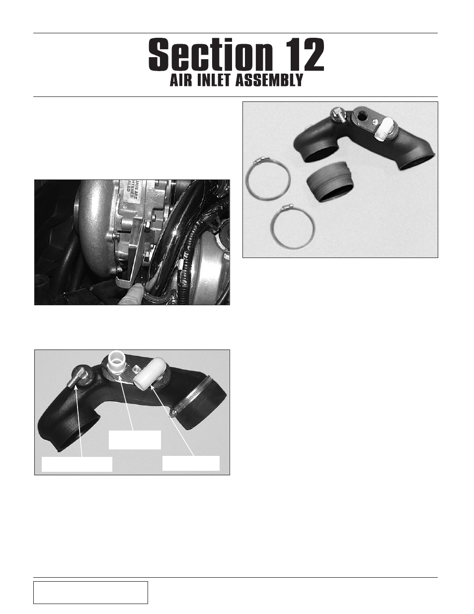
Fig. 12-b
3/4"NPT x 1" x 90°
BARBED FITTING
3/4"NPT TO 1"
BARB (H.O.
ONLY)
1/4"NPT x 3/8" x 90°
HOSE BARBED FITTING
Section 9
AIR DISCHARGE ASSEMBLY INSTALLATION
(NON-COOLED KITS ONLY)