Paxton Superchargers Ford Mustang GT User Manual
Page 54
P/N: 4809654 v5.0
©2010 Paxton Automotive
All Rights Reserved, Intl. Copr. Secured
34
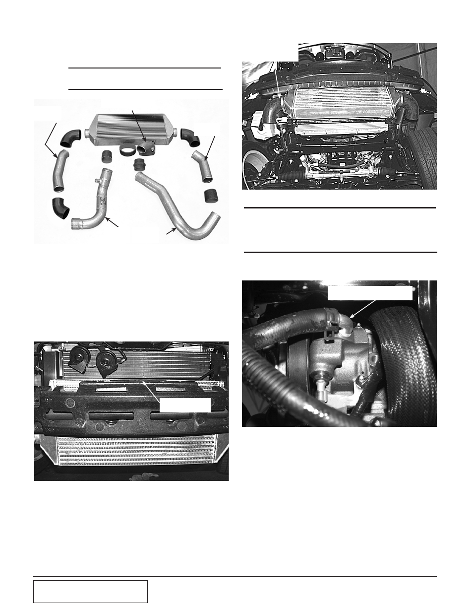
8G. CHARGE AiR CooLER CoRE iNSTALLATioN
(2007-2010 Model H.o. kits only)
Fig. 8G-c
Fig. 8G-d
SHORT ENDS OF 90°
ELBOWS PROVIDED
FITTING ROTATED TOWARD
FRONT OF VEHICLE
*** NOTE ***
Use Fig. 8G-a to aid in the next few steps
1. Locate the Charge Air Cooler assembly.
Place the cooler onto the previously
installed hardware, making sure the four
spacers remain in place. Align the top of
the cooler flush with the top of the styro-
foam bumper support. Secure the cooler
using the nuts and washers provided. (See
Fig. 8G-b.)
2. Loosely install the short ends of the two
90° rubber elbows onto each end of the
charge cooler using the supplied #48 hose
clamps. (See Fig. 8G-c.)
3. Using the Ø3" x 2.75" reducer sleeve and
clamps, loosely attach tube “A” to the
supercharger’s discharge. (See Fig. 8G-e.)
Fig. 8G-a
Fig. 8G-b
FLUSH WITH
TOP
TUBE
“A”
TUBE
“E”
TUBE
“D”
DISCHARGE
DUCT
TUBE
“C”
*** NOTE ***
For better duct clearance, rotate the power steering return fitting so
that it points to the front of the vehicle. Use care not to damage the
fitting or hose. If necessary, rotate the power steering line from the
rack to the radiator closer to the frame. (See Fig. 8G-d.)