Paxton Superchargers Ford Mustang GT User Manual
Page 62
P/N: 4809654 v5.0
©2010 Paxton Automotive
All Rights Reserved, Intl. Copr. Secured
42
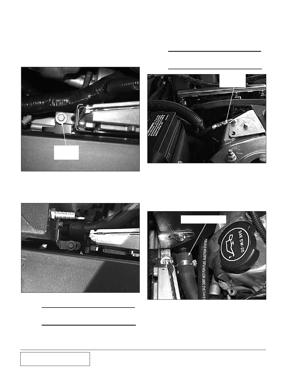
5. Remove the 10mm headed bolt that
secures the back of the ECU and the power
distribution box. (See Fig. 8K-d.)
6. Install the coolant reservoir. Secure the
front of the reservoir with the factory fas-
tener removed previously. (See Fig. 8K-e.)
*** NOTE ***
Leave this bolt loose for final adjustment in a later
step.
Fig. 8K-d
Fig. 8K-e
7. Attach the rear mounting bracket to
the strut tower with the 6mm x 20mm
long screws and washer provided.
(See Fig. 8K-f.)
*** NOTE ***
Reinstall the factory ground wire with one of the 6mm
screws and washers.
8. Attach a length of 3/4" hose (approxi-
mately 3') to the 3/4" bung on the
front of the coolant reservoir. Route
the hose to the 3/4" outlet on the ther-
mostat housing secure the hose with
the clamps provided. (See Fig. 8K-g.)
10mm
HEADED
BOLT
8k.
ENGiNE CooLANT RESERvoiR
iNSTALLATioN
(2005-2006 Model H.o. kits only),
cont’d
Fig. 8K-f
FACTORY
GROUND
STRAP
Fig. 8K-g
3/4" HOSE ATTACHED TO
THERMOSTAT HOUSING