Paxton Superchargers Ford Mustang GT User Manual
Page 65
P/N: 4809654 v5.0
©2010 Paxton Automotive
All Rights Reserved, Intl. Copr. Secured
45
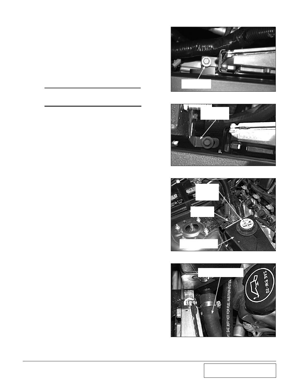
Fig. 8L-d
Fig. 8L-e
10mm HEADED
BOLT
RESERVOIR
BRACKET
Fig. 8L-f
3/4" HOSE ATTACHED
TO FACTORY 1" HOSE
Fig. 8L-g
5. Remove the 10mm headed bolt that
secures the back of the ECU and the
power distribution box. (See Fig. 8L-d.)
6. Install the coolant reservoir. Secure the
front of the reservoir with the factory fas-
tener removed previously. (See Fig. 8L-e.)
***NOTE***
Leave this bolt loose for final adjustment in a later
step.
7. Attach the rear mounting bracket to the
strut tower using the factory strut mount-
ing hardware. (See Fig. 8L-f.)
8. Attach a length of 3/4" hose (approxi-
mately 22" long) to the 3/4" bung on the
front of the coolant reservoir. Secure
using one of the #10 hose clamps provid-
ed. Route the open end of the hose to the
1" hose previously connected to the facto-
ry coolant reservoir. Connect and secure
the two hoses using the 3/4" x 1" hose
union, the factory 1" spring clamp and the
#10 hose clamp provided.
8L. ENGiNE CooLANT RESERvoiR
iNSTALLATioN (2007-2010 Model H.o. kits
only), cont’d
FACTORY
RADIATOR
CAP
RESERVOIR
BRACKET
COOLANT
RESERVOIR