Appendix – BECKHOFF AX2000 CANopen communication profile User Manual
Page 127
To start up the axes, the servo amplifiers must be put into the operational status (operation enable)
and the network management functions must be started.
The network management functions enable the application of the Process Data Objects (PDOs)
and are initialized by the following telegram for both axes:
Switch the NMT (Network Management) status machine to operation enable:
COB-ID
Command specifier (CS)
Node-ID
Comment
0
1
1
NMT enable for all axes
Next, power is applied to each servo amplifier, and they are put into the operation enable condition.
Control word for operation enable:
COB-ID
Control byte
Index
Sub-
index
Data
Comment
Low byte
High byte
601
2B
40
60
00
h
0F 00 00 00
control word for axis 1
581
60
40
60
00
h
00 00 00 00
602
2B
40
60
00
h
0F 00 00 00
control word for axis 2
582
60
40
60
00
h
00 00 00 00
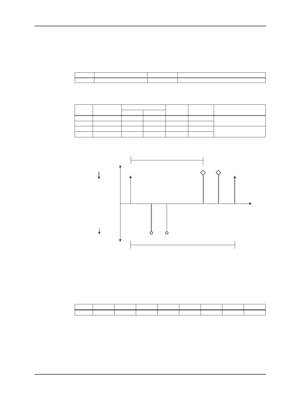
The configuration above now enables a cyclical sequence, as shown in the following diagram:
RPDO 2 can now be used to supply trajectory data for both axes, for instance:
COB-ID
Byte 0
Byte 1
Byte 2
Byte 3
Byte 4
Byte 5
Byte 6
Byte 7
301
F4
01
00
00
E8
03
00
00
In this example, the first axis receives a trajectory value of 500 increments (Bytes 0 ... 3) and the
second axis receives a trajectory value of 1000 increments.
The axes accept these values, and the positioning is made when the next SYNC telegram is recei-
ved.
CANopen for AX2000/2500
127
BECKHOFF
07/2007
Appendix
Control
Drive
Drive
Control
t cycle
Setpoint
Axis
1
Sync
Sync
Setpoint
Axis
2
Position
&
S
tatus
Axis
1
Position
&
S
tatus
Axis
2
400 μs
cycle
t
1 ms per axis at 1 MBaud
e.g. 2 axes