Wiring to earth ground – Wavetronix SmartSensor HD (101-0415) - User Guide User Manual
Page 24
CHAPTER 2 • CONNECTING POWER AND SURGE
23
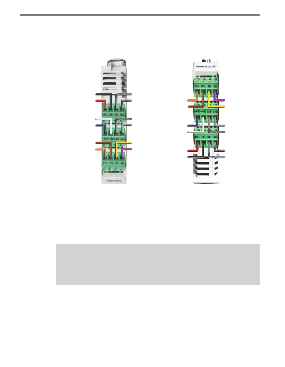
The Click 200 contains three terminal connectors on both the top and the bottom of the
module (see Figure 2.3). The terminal connectors are removable and are red-keyed, al-
lowing each connector to plug into only one specific jack. This both simplifies the wiring
process and reduces the possibility of wiring errors.
Power Drain
Ground (Gray)
RS-485 Drain
RTS (Orange)
CTS (Brown)
-485 (Blue)
+485 (White)
+DC (Red)
GND/-DC (Black)
TD (Yellow)
RD (Purple)
-DC (Black)
+DC (Red)
+485 (White)
-485 (Blue)
CTS (Brown)
RTS (Orange)
Power Drain
RS-232 Drain
RS-485 Drain
Ground (Gray)
TD (Yellow)
RD (Purple)
RS-232 Drain
Figure 2.3 – Click 200 Terminal Connections (protected and unprotected sides)
If you have an 8-conductor cable, it will have the following wiring differences:
˽
There is no gray ground wire.
˽
Instead of three drains, there is only one. This drain can be connected into any of the
screw terminals marked GND.
˽
The white +485 wire will have a blue stripe.
Note
See Appendices A and B for cable pinout diagrams for the two different connectors
found on SmartSensor HDs.
Wiring to Earth Ground
All Click 200 devices should be mounted on a DIN rail that is connected to earth ground
either through an earth-grounded chassis or a 16 AWG or larger grounding wire attached
to a 7-ft. (2.1-m) grounding rod. Follow the steps below to correctly wire to earth ground: