Wavetronix SmartSensor HD (101-0415) - User Guide User Manual
Page 8
INTRODUCTION
• SMARTSENSOR HD USER GUIDE
7
ample, sensors mounted on gantries have successfully met customer requirements when
using a 3-foot extension arm to laterally separate the sensor from the structure. Please
talk with a Wavetronix Technical Support representative about your specific situation.
˽
Mounting Height – The mounting height should be based upon the offset from the
lanes of interest. For each offset, the minimum, maximum, and best heights are shown
in Table 1.1, found in Chapter 1. In general, the range of recommended heights is be-
tween 9 and 50 ft. (2.7 to 15.2 m).
˽
Mounting Offset – The minimum recommended offset (distance from the sensor to
the edge of the first lane of interest) is 6 ft. (1.8 m).
˽
Arterial Locations – Sensor sites on arterials or other roadway segments with regulat-
ed stop lines should be selected at midblock positions to increase accuracy by avoiding
positions at which vehicles are often stopped in front of the sensor.
˽
Freeway Locations – The SmartSensor HD is often used at permanent ATR (auto-
matic traffic recorder) stations. The number of stations along a single roadway and the
distance between stations should be selected to achieve adequate levels of statistical
confidence. Permanent ATR stations, which are selected to cover interstate, principal
arterial, and other national and state highways, are used to establish seasonal adjust-
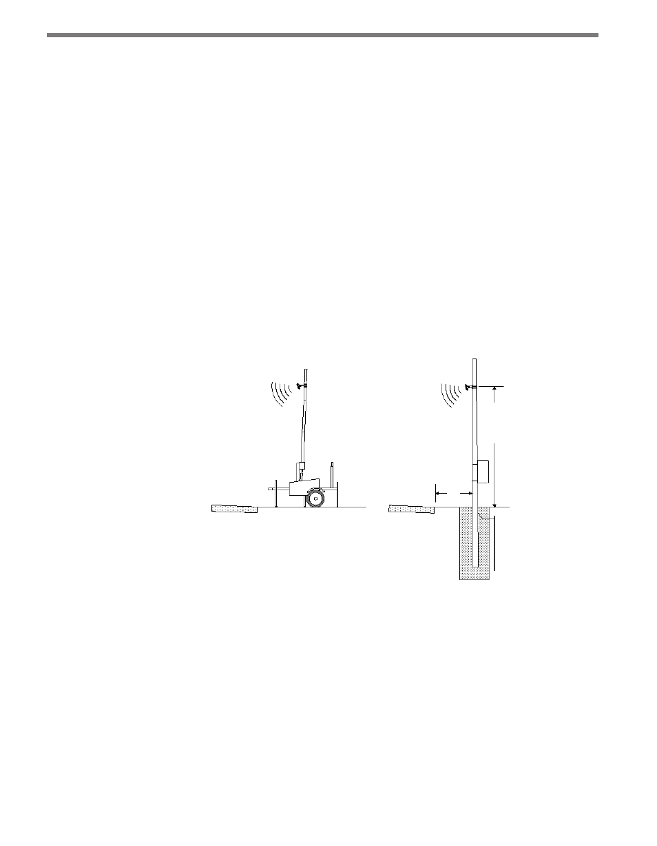
ment factors for count data from temporary collection sites (see Figure I.1).
Roadway
Roadway
9–50 ft.
6 ft.
min
(see
mounting
guidelines)
Figure I.1 – Portable (left) and Permanent (right) Sensor Stations
˽
Cable Lengths – Ensure that you have sufficient homerun and sensor cabling. Cables
can be as long as 600 ft. (182.9 m) if they’re using 24 VDC operation and RS-485 com-
munications; for longer connections, alternate wired and wireless options should be
considered.
˽
Signaling Delay – After a vehicle passes in front of the sensor there will be a slight
delay before the data for that vehicle is sent from the sensor. In a time-sensitive ap-
plication—for instance, to supply a dynamic message sign with per vehicle warning
messages—it will be necessary to ensure the sensor is sufficiently far upstream from
the sign that the system has time to collect the data, process it, and send it to the sign
by the time the vehicles reach the problem area. For specifics about signaling delay,
see Appendix E.