Appendix b - 26-pin connector – Wavetronix SmartSensor HD (101-0415) - User Guide User Manual
Page 83
82
APPENDIX • SMARTSENSOR HD USER GUIDE
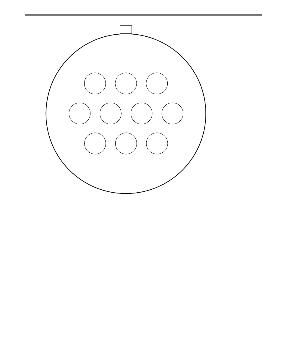
H=7
+DC
Red
A=1
-DC
Black
B
NC
G=10
232 TX
Yellow
K=11
232 RX
Violet
J=9
232 CTS
Brown
C=9
232 RTS
Orange
F=12
+485
Blue/White
E=6
-485
Blue
D=5
Drain/
shield
Figure A.1 – 10-pin Plug Connector Socket Assignment (seen from the solder cup side of the
connector)
Appendix B - 26-pin Connector
Certain SmartSensor HDs, including the HD legacy, the retrofitted HD, and the limited
lane and feature versions, have a 26-pin connector. You can order this connector on two
different cables:
˽
The 8-conductor cable, which is the same cable mentioned above; it can be ordered
with either the 10-pin connector or the 26-pin connector.
˽
The 9-conductor cable. This cable is composed of three groups of wires, each contain-
ing color-coded wires and a drain wire surrounded by a shield.
See Figure B.1 for a diagram of the 9-conductor cable’s 26-pin socket assignment. The codes
listed in the diagram are to be used to solder wires into the back of the plug where the letters
represent the individual solder cups.