Wiring communication – Wavetronix SmartSensor HD (101-0415) - User Guide User Manual
Page 30
CHAPTER 2 • CONNECTING POWER AND SURGE
29
To put power on the T-bus, you will first need to connect a 5-screw terminal block to the
end of the T-bus, then follow the steps below to wire DC to it:
1 Connect +DC (red) from the Click 201/202 to the top screw terminal on the 5-screw
terminal block.
2 Connect –DC (black) to the second screw terminal.
+24V DC
-DC
(red wire)
(black wire)
Green
Gray
+485
-485
GND
Figure 2.8 – Connecting Power Directly to the T-bus
Note
Green T-bus connectors conduct power and communication on the DIN rail backplate;
gray T-bus connectors only conduct power and are used to distribute power without
connecting communication.
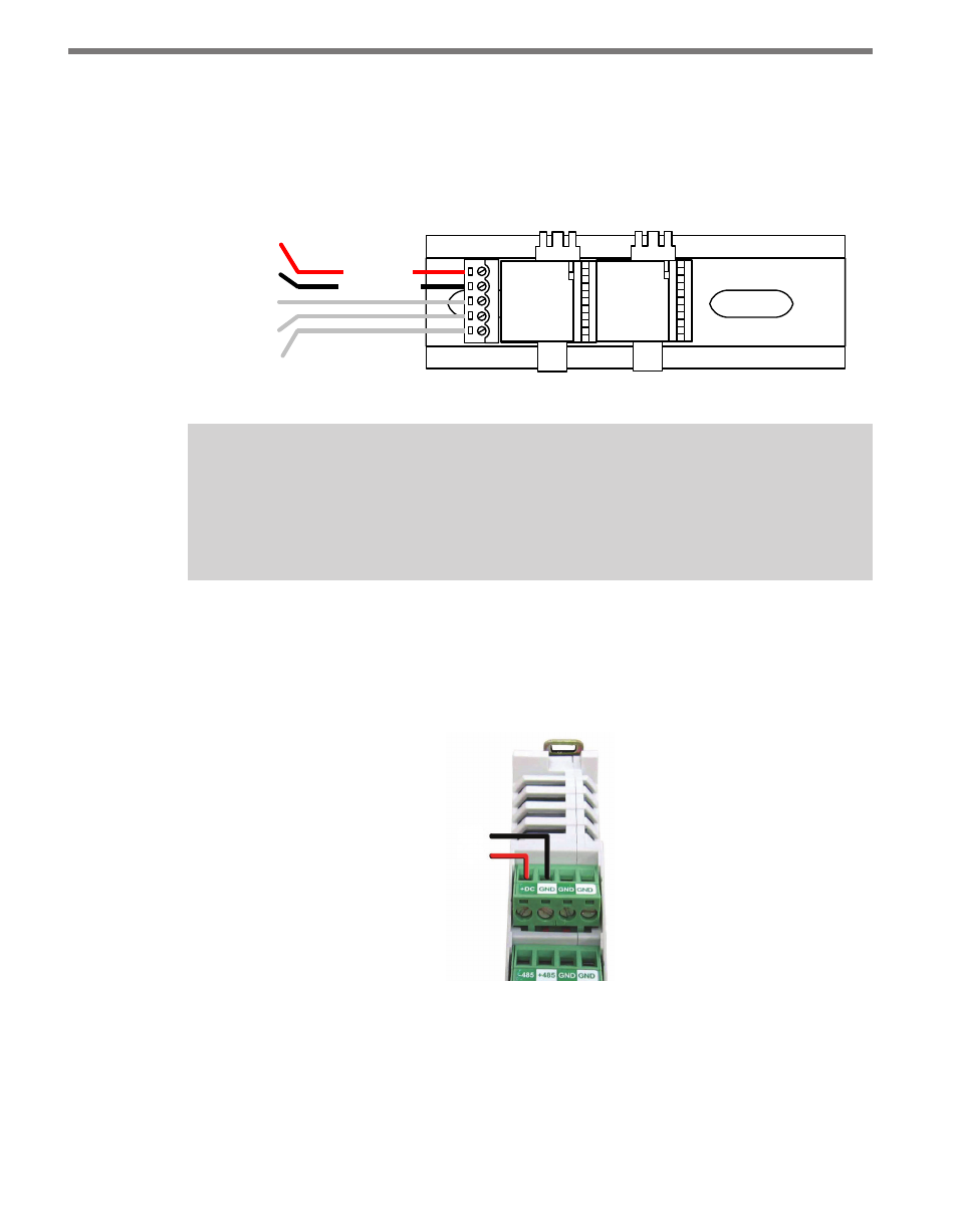
You can also wire DC to the Click 200 itself; it will then put that power on the T-bus. If you’d
like to do that, follow these steps:
1 Connect +DC (red) from the Click 201/202 to the +DC screw terminal.
2 Connect -DC (black) to a GND screw terminal.
GND
+DC
Figure 2.9 – Wiring DC Power into the Click 200
Wiring Communication
The last thing to do is decide how to communicate with the sensor. How you do this will
vary based on your installation. If your sensor is connected to a Click 200 in a pole-mount