Connecting the power plant to your installation – Wavetronix SmartSensor HD (101-0415) - User Guide User Manual
Page 29
28
CHAPTER 2 • CONNECTING POWER AND SURGE
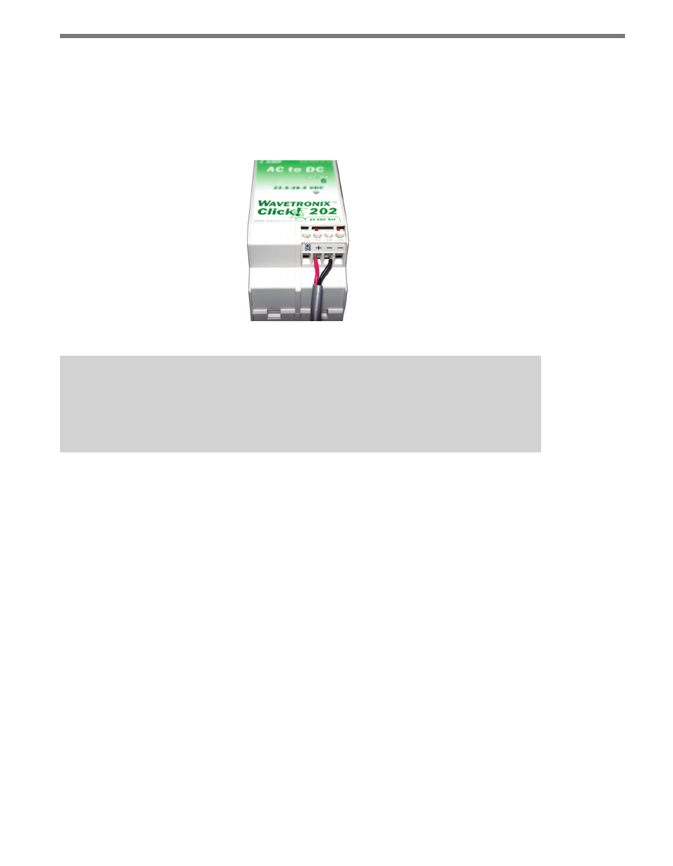
To wire the newly converted DC power out of the Click 201/202:
1 Connect a +DC conductor (usually a red wire) to the + screw terminal on the bottom
of the Click 201/202 (see Figure 2.7).
2 Connect a -DC conductor (usually a black wire) to either of the – screw terminals on
the bottom of the Click 201/202.
Figure 2.7 – Wiring DC Power Out of the Click 201/202
Note
Do not wire into the screw terminal marked DC OK; it provides only 20 mA and should
be used only for monitoring the power supply.
The screw terminal connectors on the top and bottom of the module are removable to sim-
plify wiring and are red-keyed, allowing the connector to plug into only one correct jack.
Connecting the Power Plant to Your Installation
Now the power plant is complete and you have reliable, safe DC power. The next step is to
get that power to the rest of the installation.
If the power plant is in a pole-mount box, this involves getting that power onto the T-bus; from
there it will power any communication devices that may be on it. It will also power the Click 200,
which will send the necessary 10–30 VDC, along with communications, to the sensor.
If the power plant is in a main traffic cabinet, this also will involve getting DC from the
power plant on the T-bus; from there it will power any communication devices on that bus.
It will also power the Click 200, which will send that power, along with communications,
along the homerun cable to the Click 200 in the pole-mount box. That Click 200 will put
the power (and communications) onto the T-bus, powering any communication devices
that may be on it. It will also send the necessary 10–30 VDC, along with communications,
to the sensor.