Wavetronix SmartSensor HD (101-0415) - User Guide User Manual
Page 28
CHAPTER 2 • CONNECTING POWER AND SURGE
27
3 Connect the neutral (usually white) wire from the AC terminal block or cord to the
terminal marked 1 on the Click 230.
4 Connect the ground wire from the AC terminal block or cord to the terminal marked
3 on the Click 230.
5 Connect an outgoing and protected line wire to the terminal marked 2 on the Click
230. The line wire should be black.
6 Connect an outgoing and protected neutral wire to the terminal marked 6 on the Click
230. The neutral wire should be white.
The terminal blocks 3 and 4 are directly bonded via the metal mounting foot of the base
element to the DIN rail. There is no need for any additional grounding between terminals
3 and 4 and the DIN rail.
Wiring the Click 201/202
The final device in the power plant should be either a Click 201 or 202 (as shown in Figure
2.5). These are AC to DC converters, also occasionally called the power supplies. As noted
above, the difference between the two is that the Click 201 outputs 1 A and the Click 202
outputs 2 A (the Click 204 outputs 4 A but will probably not be needed for an HD installa-
tion). Choose which device suits your installation best, then follow the steps below to install
it (see Figure 2.6):
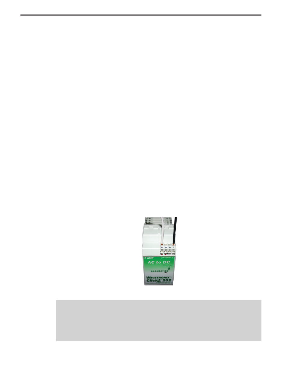
1 Mount the Click 201/202 onto the DIN rail next to the Click 230.
2 Connect the line (black) wire from the Click 230 into the L screw terminal on the top
of the Click 201/202.
3 Connect the neutral (white) wire from the Click 230 to the N screw terminal to the top
of the Click 201/202.
Figure 2.6 – Wiring AC Power into the Click 201/202
Note
The NC screw terminal is not connected internally. Connecting a wire to a no connect
(NC) terminal simply gives it a convenient termination point.