Yaskawa VS-616G5 Series Revision F Programming Manual User Manual
Page 100
100
VS-616G5 Programming Manual
Section H: Control Circuit Terminals
H4 Analog Outputs
Setting Range:
-10.0 to 10.0%
Factory Default:
0.0%
Sets the terminal 21 output bias for the analog output monitors. To obtain the output level, multiply the
monitor output level by the gain value set in H4-02, then add the bias value set in H4-03.
Selects the analog output monitors for terminal 23 (see Terminal 21 Analog Output Selection). The
resolution of terminal 23 is 9 bit plus sign.
Setting Range:
0.00 to 2.50
Factory Default:
1.00
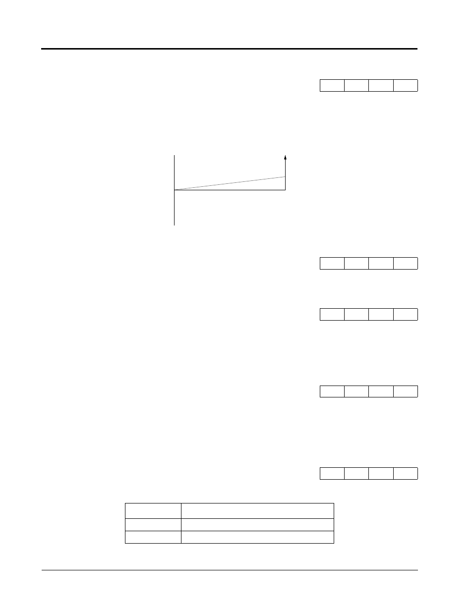
Sets the terminal 23 output gain for the analog output monitors. To obtain the output level, multiply the
monitor output level by the gain value set in H4-05. See Figure 48.
Setting Range:
-10.0 to 10.0%
Factory Default:
0.0%
Sets the terminal 23 output bias for the analog output monitors. To obtain the output level, multiply the
monitor output level by the gain value set in H4-05, then add the bias value set in H4-06. See Figure 48.
Selects the type of voltage signal output at terminals 21 and 23.
H4-03 Terminal 21 Analog Output Bias
Terminal 21 Bias
B
B
B
B
H4-04 Terminal 23 Analog Output Selection
Terminal 23 Sel
B
B
B
B
H4-05 Terminal 23 Analog Output Gain
Terminal 23 Gain
B
B
B
B
H4-06 Terminal 23 Analog Output Bias
Terminal 23 Bias
B
B
B
B
H4-07 Analog Output Signal Selection
AO Level Select
B
B
B
B
Setting
Description
0
0 to 10V input (factory default)
1
-10 to +10V input
Figure 48 Analog Output Gain and Bias Adjustment
+10
-10
0
Bias (%)
0
Reference (%)
2.50
Gain
1.00