Yaskawa VS-616G5 Series Revision F Programming Manual User Manual
Page 65
VS-616G5 Programming Manual
65
V/f
V/f w/PG Open Loop
Vector
Flux
Vector
This parameter is effective only when the printed circuit board PG-B2 is used
Selects whether speed control (ASR) integral operation is activated during acceleration/deceleration.
Setting Range:
0 to 120%
Factory Default:
115%
Sets the motor overspeed detection level as a percentage of maximum output frequency (E1-04).
Setting Range:
0.0 to 2.0s
Factory Default:
0.0s
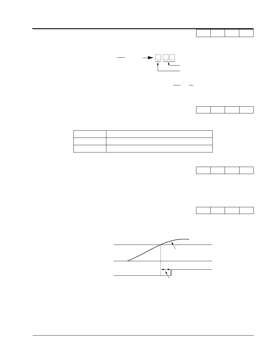
Sets the elapsed time from when an overspeed condition is detected to when a fault occurs.
A fault signal is output to stop operation after the absolute value of the motor speed exceeds the set
value of F1-08 and after the time set to F1-09 elapses. The stopping method is set by F1-03.
When parameter A1-02=1 [V/f w/PG] the factory setting will be 1.0. When parameter A1-02=3 [Flux
Vector] the factory setting will be 0.0.
F1-07 Integral Value During Accel/Decel
PG Ramp PI/I Sel
−
B
−
−
Setting
Description
0
Integral operation disabled (factory default)
1
Integral operation enabled
F1-08 Overspeed Detection Level
PG Overspd Level
−
A
−
A
F1-09 Overspeed Detection Time
PG Overspd Time
−
A
−
A
Division Ratio =
n + 1
m
Data
m: 1 to 32
n: 0, 1
Setting Example:
When F1-06 is set to “132”, then the division ratio =
1 + 1
32 =
2
16
Figure 29 Overspeed Detection Timing Diagram
Overspeed Level (F1-08)
OFF
ON
|
Motor Speed
|
F1-09
Overspeed Fault Signal
0
Section F: Option Parameters
F1 PG Option Set-up